
Battery isolation, complete lever-and-pin retention and distinct signals
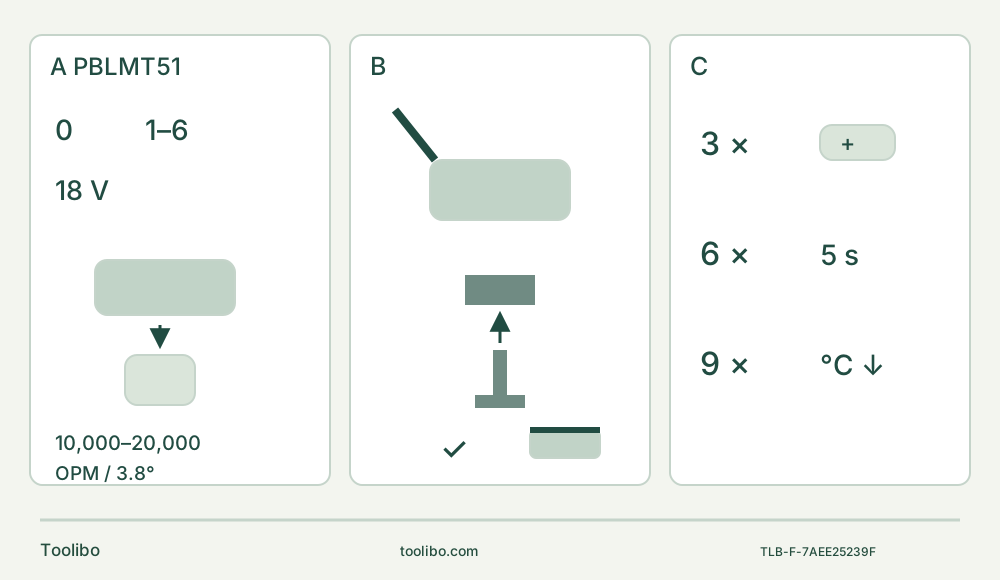
Three panels show an isolated 18 V body with dial 0 and settings 1–6, the released lever and push-in locking pin followed by closed-lever retention, and three separate flash-response cues.
A · Qualify power and isolate
Use only the already-commissioned supplement-listed system and its actual instructions. Remove the pack, clear any trigger latch and set dial 0 before setup; both pack latches must secure before a later start.
B · Finish the mechanical sequence
Lift through raised to unlocked, remove the cooled pin, fully engage the actual accessory, push the pin until it clicks and lower the lever to locked. Check retention while isolated; do not infer security from housing movement.
C · Complete the sample, then respond safely
Use momentary trigger control on clamped visible wood, stop and remove the pack for acceptance. Treat each LED pattern distinctly, correct the underlying setup while isolated and stop for persistent faults rather than reproduce them.
Original schematic with neutral uncounted mounting features. A separates the battery: 0 is lockout, not physical isolation, and the numbers do not show a direction of dial rotation. B needs the lever beyond raised to unlocked, full engagement, pin click and locked lever; no pin turn or tightening torque. C means 3 flashes low battery, 6 excessive force with a five-second wait, and 9 cooling; the battery symbol is not a charging recipe and the temperature cue is not a threshold. More than 9 and persistent faults are addressed in the body.
Start with the exact body, not a kit nickname
Use this workflow only for the US PBLMT51 matching the current linked operator’s manual 999000265, 5 March 2026, REV04. The official PBLMT51B product’s support service links that document, whose cover also names PBLMT51SB30. This is one PBLMT51 owner system, not separate tool-only, kit and suffix model counts. Match the actual nameplate and applicable instructions; do not substitute the older PBLMT50 or a screw-mounted multi-tool’s procedure.
The completed task is a short straight cut in a clamped, visible piece of new uncoated solid softwood, followed by battery-out acceptance. It is not an installed trim repair, a hidden-service cut or a metal trial. The current manual’s general-purpose plunge blade table authorizes straight cutting in wood and plastic. Use the actual original or manufacturer-recommended identified wood blade with its own instructions and sufficient installed reach. REV04 does not supply a blade part number here; this guide will not invent one. Older REV01 segment-blade pictures and current broad marketing claims are not the selected accessory’s operating authority.
Qualify power before mounting anything
The manual requires batteries and chargers listed in correlation supplement 987000-432. This article is for an owner whose exact approved system has already been commissioned using that supplement and the actual battery and charger instructions. If those documents, the approved combination or the condition of the equipment are uncertain, stop before powered work. A generic ONE+ statement does not replace the list, and no new named pair or charging recipe is inferred here.
Use a sound, undamaged pack and tool. The manual specifies dry use and excludes use, storage or charging below 50°F or above 100°F; do not store outside or in a vehicle. Follow the actual battery and charger instructions as well. Do not use a battery pack or charger that has been dropped or received a sharp blow. Follow the actual battery instructions and qualified-service guidance for safe disposition, without attempting a trial or home repair. A damaged or modified pack or unreliable switch is likewise not a trial-cut problem. Do not open or service a battery.
With the pack removed, identify the trigger, side lock-on button, top speed dial and front blade-release lever. The dial’s fully right-hand 0 position is a lockout: it prevents operation but does not physically isolate an installed battery. For accessory work, adjustments, cleaning and storage, remove the pack. Press and release the trigger while isolated to clear a possible latched lock-on, release it fully, and leave the dial at 0 before insertion preparations.
Open beyond raised, then complete the pin clamp
Keep the battery out and allow a used blade and locking pin to cool. Handle the sharp accessory carefully with suitable protective gloves; keep them away from moving parts during use. Lift the blade-release lever to its raised position, then continue to the unlocked position. The manual says extra resistance at that second stage is normal. Merely raising the lever is not the full release sequence.
Remove the locking pin. Seat the accessory so the openings in its mounting base fully engage the raised features on the head. Reinsert the pin until it clicks securely into place, then lower the lever to its locked position. Check that the correct accessory is securely retained before continuing. This is a push-in pin and closing lever, not a threaded tightening procedure; do not add a washer, turn the pin through a borrowed angle, guess a torque or modify an incompatible mounting opening.
REV04 notes that the blade base can move slightly within the housing to reduce transmitted vibration. That designed movement is not permission to accept an insecure accessory, a damaged clamp or a pin that will not click into place. If the documented assembly will not secure the actual recommended accessory, keep the pack out and obtain qualified service. Never use an energized wobble test to decide whether retention is acceptable.
Make the sample and control path ready
Inspect both faces of the known wood and clear the entire area below the intended cut. Reject nails, screws, coatings, foreign material or an unknown history for this exercise. Mark a short route that fits the actual blade’s usable reach and full swept envelope. Clamp the retained piece to a stable platform; independently support the waste so it cannot shift the work or pinch the blade. Keep clamps and support outside the blade path. Do not hold the stock in your hand or against your body.
Rehearse the grip and approach with the battery removed. Hold the tool firmly in front of and away from the body, on the insulated gripping surfaces. Keep the trigger controllable and both hands clear of the blade, its underside and the waste. Do not reach around or over a moving blade. Tie back hair and keep loose clothing or jewelry away from the tool and air vents. The source’s correct-grip illustrations do not authorize leaving the stock unsecured.
Wear side-shield eye protection marked ANSI Z87.1 for assembly, use and maintenance. Use hearing protection and suitable dust protection for the work, with effective dust controls where provided and appropriate ventilation. If the sample cannot be held and approached without compromising these conditions, change the sample or do not proceed.
Understand momentary operation before fitting the pack
The trigger starts the tool when depressed and stops it when released, unless lock-on is engaged. To latch, the manual describes holding the trigger, holding the side button, releasing the trigger and then releasing the button. To cancel that latch, press and release the trigger. This short controlled cut uses momentary trigger operation; do not deliberately latch it on. Still know the cancellation action in case the latch has been engaged.
Confirm the trigger is released, the latch cleared and the dial fully right at 0. Insert the approved pack into its port and verify that both latches snap securely into place. The dial positions 1–6 set the maximum speed: 1 is low, turning left selects higher settings and right selects lower settings. The stated tool range is 10,000–20,000 OPM with a 3.8-degree oscillation angle; it is not an exact rate table for the six positions. No universal numbered wood setting is supplied. Choose a controlled setting appropriate to the actual blade and sample, without exceeding any accessory limit. For this project, change settings with the trigger released and tool stopped.
Start clear of the wood and let the blade reach the selected full speed before entering the marked cut. Maintain light cutting pressure. With the teeth in the work surface, move the back of the tool slowly in a constant sideways motion as described by the manual; this is controlled feeding, not twisting the blade in a tight kerf or levering out a bridge. Excess force can create strong vibration, break a blade and accelerate motor wear. Do not use blurred blade lettering as a reason to ignore binding, changing support or abnormal behaviour.
On completion, release the trigger, ensure lock-on is not maintaining motion, turn the dial fully to 0, wait for complete stop and remove the battery before handling the sample. Do not remove cut material while the blade moves. Allow hot parts to cool before changing the accessory.
Accept the sample only if the intended cut is complete, the retained piece follows the marked purpose and there is no uncontrolled tear-out, scorch or evidence that support moved. Check attachment condition while isolated. A remaining bridge or poor cut requires a corrected, re-clamped setup or qualified assessment, not force beside a powered blade. No manufacturer tolerance or structural fitness is implied.
Separate the LED messages from permission to restart
The front worklight illuminates with the trigger and times out when idle; darkness is not proof of isolation. REV04 gives distinct flash patterns: 3 indicates low battery, 6 excessive force with a five-second wait, and 9 overtemperature requiring cooling. More than 9 flashes calls for removing the battery and reinserting it a few minutes later. No LED colour is specified here.
These are response instructions, not diagnostic tests to provoke or repeat. Release the trigger, return to 0 and isolate before correcting the work or changing a pack. For six flashes, waiting alone does not correct excessive feed or a trapped blade. For nine flashes or a thermal shutdown, let the motor cool; the manual says it will not operate until cooled. Its separate advice about full-speed unloaded cooling after prolonged low-speed operation does not override a thermal cutoff or justify running a faulty tool. Persistent faults, abnormal vibration or doubtful retention mean stop and service, not repeated insertions or repeated stalls.
Keep any later sanding task separate
To change to the matched detail pad, stop, set 0, remove the pack and use the complete lever/pin sequence again. Fit correctly sized, suitable sandpaper; REV04 identifies a 120-grit sheet in its accessory table but does not make that the right finish for every surface. Work only on known clean material with suitable dust protection. The sanding instructions start the tool clear, let it reach full selected speed, then lower it gently and move continuously with the tool’s weight rather than added force. Lift it from the surface before switching off, then isolate before inspection. Do not remain on one spot or transfer an unknown coating-removal task into this wood exercise.
After the cutting project, clean plastic surfaces with clean cloths rather than solvents, protect the isolated tool and pack during storage, and use qualified service with identical replacement parts where needed. Supply the actual model and serial number; do not open the internal vibration-isolation or clamp assemblies yourself.
Source basis: PBLMT51/PBLMT51SB30 operator’s manual 999000265 REV04, English pages 2–8, actual illustrations 10–11 and back page; exact current US product and official support manual response. This is a documentation-based workflow, not a hands-on comparison, battery-capacity test or kit-content guarantee.
Models referenced