
Four gates for the screw-holder and standby system
Four panels show battery-out screw/washer/hex-key installation with neutral locating segments, lock-on cancellation and dial 0 before pack insertion, supported cutting and separate flat-pad sanding, and distinct 3/6/9 flash responses.
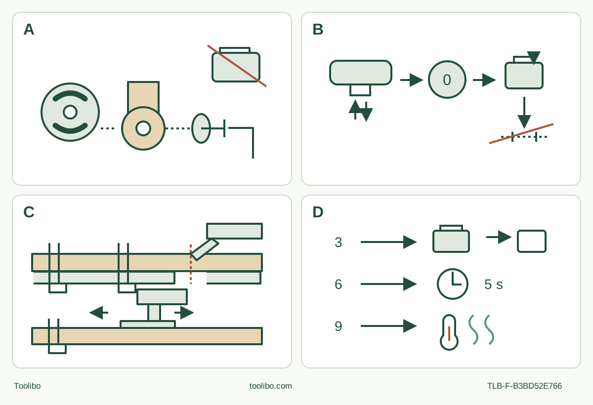
A · Remove power and engage the holder
Remove the pack, undo the screw and washer with the stored key, fully engage the accessory openings on the raised head features, refit and tighten securely, then store the key.
B · Clear lock-on before insertion
Depress/release the trigger, leave it released and turn clockwise to the 0 click before inserting the qualified pack and checking both latches. Remove the pack for isolation.
C · Complete the visible wood trial
Clamp/support clean wood with full blade clearance and use the exact listed blade. Start clear, use controlled pressure, stop and remove the pack for acceptance; sanding needs its own complete approved pad/sheet setup.
D · Distinguish 3, 6 and 9 flashes
Three means low battery, six excessive force with a five-second wait and cause correction, nine overtemperature requiring cooling. More than nine requires the manual’s stopped pack-removal/reset route, not repeated forcing.
Original schematic, not counted locator geometry or measured clearances. B summarizes the pre-insertion checks, not a claim that 0 disconnects the battery. C’s lower flat-pad setup is a separate sanding permission, not a second required stage of the wood cut. D’s five-second wait for six flashes does not cure binding; thermal cutoff still requires cooling.
Match the dated screw-holder body first
This guide completes a short, visible cut in loose untreated softwood with the US RYOBI PCL430 and its directly mounted general-purpose plunge blade. It is scoped to operator’s manual 998000591, dated 8-6-25, REV:05, and an actual body and supplied instructions that match it. The current PCL430B product confirms the model family, but a current product-to-this-exact-revision download link has not been established. Do not read this as a latest-supplied-manual or current-kit claim.
The PCL430 has an 18 V battery system, a hex-screw and washer attachment, a trigger, a side lock-on button and a speed dial whose 0 position is STANDBY. It is not a tool-free PBLMT body. The documented range is 10,000–20,000 oscillations per minute with a 3° oscillation angle. These figures do not establish a universal blade, battery or cutting-depth permission.
The project ends in an isolated acceptance check of the intended cut. It excludes installed trim, concealed services, coatings, unknown adhesives and metal cutting. Although the general applications mention thin metals, the exact general-purpose blade’s table authorizes wood and plastic; generic tool capability cannot broaden that blade’s material approval.
Require the actual approved power evidence
The manual expressly requires batteries and chargers listed in correlation supplement 987000-432. This guide has not independently selected a named pack/charger pair. Proceed only with an already commissioned actual approved combination, the matching supplement and the complete instructions for that battery and charger. If you cannot establish those conditions, obtain the correct documents from RYOBI before powering the tool. ONE+ branding alone does not replace the required correlation check, and this article is not a charging tutorial.
Inspect the battery, charger and tool for damage or modification. A dropped or damaged battery, damaged switch, incomplete housing or missing fastening component is a stop. Do not repair or open a pack, short its terminals with loose metal or expose it to heat or water. This manual prohibits use, storage or charging below 50°F or above 100°F and storage outdoors or in vehicles. The exact pack and charger instructions remain additional requirements.
Before fitting a battery, depress and release the trigger to clear any lock-on state, leave the trigger fully released and turn the dial fully clockwise until it clicks into 0. Never leave lock-on engaged at 0. For assembly or inspection, remove the battery completely: press the pack latches and withdraw it. STANDBY is not physical isolation, and the presence of a trigger does not make a battery-connected tool harmless.
Identify the listed blade and prepare the sample
REV05 lists general-purpose plunge blade 681458028, sanding backing pad 303590006 and 120-grit sheet 902424001. This project uses the exact wood/plastic plunge blade for known clean wood. Check the actual accessory identity, material instructions and condition. Do not infer that an older segment blade, a product-page upsell or a similarly shaped cross-brand accessory is included or approved.
Some accessories need an adapter; the manual directs the owner to the manufacturer and the accessory’s instructions. That is not permission to improvise a spacer or call the holder universally compatible. If the selected accessory does not directly seat as specified, stop and resolve the exact approved assembly before proceeding. The workflow below does not use an adapter.
Mark a small cut whose intended line and finished size are clear. Inspect both faces and the entire path for nails, screws and other foreign material. Clamp the sample to stable support, leaving the full blade depth and moving envelope clear of the bench and clamps. Support the retained piece and arrange waste so it cannot fall unexpectedly or pinch the blade. Never hold the work in a free hand or against your body, and never reach beneath or around a moving blade.
Choose an approach that keeps the tool firmly controlled in front of and away from you. Wear ANSI Z87.1 eye protection with side shields during setup, operation and maintenance, plus appropriate hearing and dust protection. Keep hair, clothing and bystanders clear, provide good light and dust control, and keep the grip and vents unobstructed. If the required cut cannot be reached without forcing the blade or touching a support, revise the setup rather than treating a nominal accessory size as a depth guarantee.
Remove the screw and washer, then engage the actual locating features
Keep the battery out. Remove the stored hex key from the tool’s base and turn the attachment screw counterclockwise. Remove the screw-and-washer assembly and set it where both components cannot be lost. Inspect the blade, holder and hardware; do not use a cracked or bent accessory or damaged fastening parts.
Place the accessory on the head so its openings fully engage the raised parts. It must sit correctly, not balance on top of a locator. Reinstall the matched screw and washer, tighten securely with the hex key, and check retention while still isolated. The manual gives no numerical torque, pin count or extra locking compound; do not invent one. Return the key to its storage position before operation.
A blade that cannot be seated and secured correctly needs correction or qualified service, not a powered wobble test. Every later angle change or replacement repeats battery removal and the complete fastening procedure. Allow a hot accessory to cool before handling it, and keep fingers away from sharp teeth.
Understand the dial, trigger and lock-on as separate controls
After the mounting and workholding checks, clear lock-on by depressing and releasing the trigger again. Leave it released, confirm the dial’s 0 click and insert the qualified battery. Both pack latches must snap into place and the pack must be secure before use.
Turning the dial counterclockwise moves out of STANDBY and selects higher settings through 1–6; clockwise reduces the setting. Squeezing the trigger then begins motion. To stop ordinary operation, release the trigger and turn the dial fully clockwise back to 0. The manual does not give exact per-number frequencies or a numbered recipe for this particular sample. Select a setting appropriate to the actual blade and known wood, and trial the setup on matching scrap.
Lock-on changes the stopping behavior. With the trigger depressed, push and hold the side lock-on button, then release the trigger to continue running. To release that latch, depress and release the trigger. Do not use lock-on where the tool may need to stop suddenly. This short cutting trial uses momentary trigger operation, not lock-on; understanding the cancellation remains essential in case it was left engaged.
The work light illuminates with trigger depression. If it flashes while the dial is at 0, the manual says to check lock-on by depressing and releasing the trigger, remove the battery, and reinstall only after the condition is corrected and the safe insertion checks are repeated. A flashing light in standby is not a safe-storage state. Remove the pack whenever the tool is not in use.
Cut under control and inspect the isolated result
With the blade clear, choose the setting and squeeze the trigger. Let it reach the selected full speed before entering the work. Keep the teeth working in the cut and use the manual’s small, slow, continuous sideways movement of the rear of the tool to help cutting progress. Do not turn this into side levering of a trapped blade. Apply only enough pressure to maintain cutting; forcing it can cause strong vibration, broken blades and motor wear.
Keep the support arrangement unchanged. Do not touch or remove waste while the blade moves. If the work shifts, the blade binds, the accessory loosens, or smoke, unusual heat or vibration appears, release the trigger or cancel lock-on, return the dial to 0 and wait for stop. Remove the pack before checking the setup. Do not use repeated stalls as a cutting technique.
At completion, cease cutting contact under control, release the trigger, set 0 and wait for complete stop before laying the tool down. Remove the battery before clearing waste, touching the blade or inspecting the cut. Accept the sample only if the intended line and size are achieved, the required cut is complete, and there is no uncontrolled tear-out, scorching or evidence of shifted workholding. If these conditions fail, reject the setup and correct the support, blade or feed before another trial. No numerical tolerance or permission for installed hidden work is implied.
Keep the three error counts and thermal cutoff distinct
The front LED’s troubleshooting chart gives three flashes for low battery, six for excessive force and nine for overtemperature. For low battery, stop and use the qualified replacement/charging route—not an unverified pack. For excessive force, the table requires waiting five seconds; also correct the pressure or binding cause before any deliberate restart. Waiting alone does not fix a trapped blade. Nine flashes requires letting the tool cool.
The separate thermal-protection instructions say to release the trigger and let the motor cool after automatic cutoff; it will not operate until cooled. The manual’s ordinary low-speed no-load cooling hint must not override thermal shutdown. This guide provides no powered cooldown procedure, no temperature bypass and no repeated restart recipe.
For more than nine flashes, the manual calls for battery removal and reinsertion a few minutes later. Treat that as a deliberate stopped reset with the full lock-on/0/insertion checks, not permission to ignore damage, unusual heat or a recurring error. A fault that persists after the specified checks goes to qualified service. A solid lamp is the chart’s normal state, not proof that the blade, pack or workholding is safe.
Sanding and care do not inherit the cut’s approval
If you later choose sanding, stop, set 0 and remove the battery before replacing the blade with the exact approved pad and its screw/washer assembly. Fit correctly sized, matching intact paper; the listed sheet is 120 grit. The actual surface determines grit and abrasive choice. Start clear, let the motor reach its selected operating speed, lower gently and keep moving. Use the tool’s weight rather than extra pressure, and lift from the surface before stopping. Do not use bare-pad contact, oversized paper or unknown painted surfaces as an extension of this wood-cut trial.
For cleaning or storage, remove the battery, keep it protected from short circuits and follow the stated temperature limits. Clean plastic with clean cloths rather than solvents, keep controls and vents free of debris, and do not open the motor or holder for improvised repairs. Service uses identical replacement parts and qualified personnel. The completed outcome is this visible, accepted sample and an isolated stored tool—not a blanket qualification of every advertised accessory.
Source basis: PCL430 operator’s manual 998000591, 8-6-25 REV:05, full English pages 1–9, shared illustrations printed 10 and back-page revision. Current PCL430B identity is confirmed separately; the exact current manual backlink and a newly selected power pair remain unclosed, so the dated body/manual and owner-supplied power-evidence gates are mandatory.
Models referenced