
Reference contact controls the depth example
Panel A shows a hypothetical 18 mm board, 6 mm intended shallow cut and 12 mm planned remainder with the stop supported on the top face. Panel B rejects an unsupported foot beyond an edge.
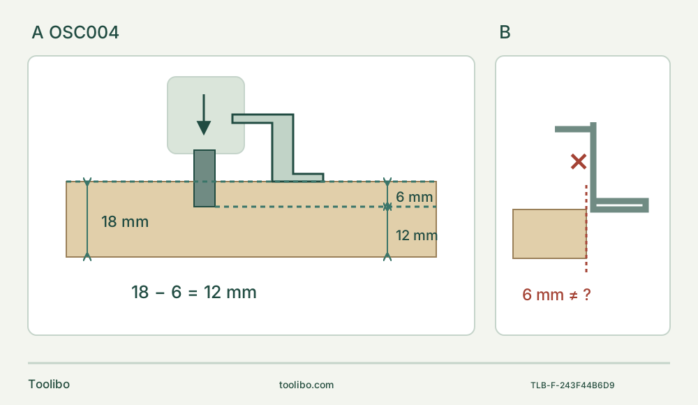
A · Supported reference and checked arithmetic
Only after measuring the actual sample and checking reach, support and the complete envelope can a shallow trial be planned. The example 18 − 6 = 12 mm does not validate any actual cut.
B · Lost contact means stop
If the narrow foot runs off the face or spans a void, stop, wait and remove the battery. Correct the supported geometry or choose another method; do not rely on the old setting.
Original schematic, not scaled assembly instructions. The numbers are hypothetical measured-project examples, never tool capacity or a safe residual-thickness rule. A assumes intact continuous reference contact and actual setup verification; B shows that losing that contact invalidates the nominal 6 mm setting. Measure the isolated trial, not the drawing.
A depth-limited trial, not permission to cut a hidden panel
This project uses the US Bosch GOP18V-34 with its matched March 2023 operating instructions, an actual OSC004 depth-stop kit and an identified Bosch OSL114 HCS wood plunge blade. It makes a short partial-depth trial in a known loose, uncoated solid-softwood panel. Both faces and all space beneath the cut must be visible and inspectable. Do not use the exercise to justify cutting an installed wall, door, floor or furniture panel with hidden contents.
The objective is to establish whether the complete stop, blade, tool and support arrangement produces the intended shallow cut on scrap, without moving the work or losing the stop’s reference surface. It is not a calibrated depth guarantee. The OSC004 limits travel through contact; it does not detect services, identify material, prevent every overcut or replace control of the blade.
Decide whether the example geometry is actually usable
The illustration uses a hypothetical measured 18 mm panel and a 6 mm trial depth. The arithmetic leaves 12 mm below the planned cut. Those are project examples, not Bosch capacity, minimum safe thickness, a required margin or a recommended setting for your work. Measure the actual sample and choose a shallow non-through target appropriate to its condition and the actual blade/stop reach.
Check the complete cut envelope, including the blade’s motion, its usable cutting length, the support underneath and the stop’s contact footprint. Keep clamps and the bench out of the blade path. A shorter blade, changed accessory orientation or different stop setting requires a new isolated check; the old setting is not automatically retained accurately.
The contact surface must be sound and sufficiently continuous for the narrow stop to remain supported throughout the planned movement. Do not let its foot run off an edge, bridge a void, rest on loose debris or ride on a clamp. Panel B in the figure shows that failure: once the reference contact disappears, “6 mm” no longer describes a controlled travel limit. If that contact cannot be maintained while holding the tool properly, stop and choose another method.
Qualify the exact body, blade and existing power system
Match the actual GOP18V-34 and supplied instructions. Its model-specific table admits OSL and OSP accessories, not OSM, even though some general material tables contain OSM examples. Use the actual intact OSL114 suitable for wood and rated at least 21,000 OPM. That accessory rating is required despite the tool’s 20,000 OPM maximum. Do not substitute an unidentified included blade, adapt a different interface or infer nail-cutting capability.
Use only the actual undamaged, already commissioned battery/charger combination covered by the matched GOP18V-34 list and its complete component instructions. The 03/2023 list explicitly names BAT612, GBA18V40, GBA18V80 and GBA18V120 packs and the specified chargers. This is an existing-owner power prerequisite, not a new charging lesson or approval of every pack carrying a platform logo. Missing identity or instructions means pause.
Select the slide fully backward to 0/OFF and wait for stop. Completely remove the battery: press its release and slide forward, then press again and withdraw fully past the secondary latch. Partial release is not isolation. Keep the battery out for all bracket, guide, blade and depth changes.
Install the stop in the documented order
Wear protective gloves for accessory handling and all work, let hot parts cool and keep fingers clear of the clamp and blade. Inspect the OSC004 bracket, clamp, guide and depth adjustment, plus the blade and tool holder. Cracks, distortion, missing pieces, slipping adjustment or uncertain retention are a parts/service hold. No arbitrary shim, extra fastener or tape repair belongs in this assembly.
The matched manual’s page 19 sequence is specific:
- Remove an already fitted accessory. Open the tool’s accessory release lever to eject it into a safe landing area; do not catch a sharp or hot blade.
- Place the OSC004 bracket on the tool nose with the bracket clamp facing the rear of the tool.
- Press the bracket clamp shut.
- Insert the appropriate guide into the front opening of the bracket.
- Install the blade on the tool.
- Use the red side button to set the desired cutting depth.
For this straight plunge blade, select the narrow stop shown in the actual Figure E. The wide stop is for round/segment-blade plunge cuts and the other illustrated guided-cut arrangement, not a part to swap casually because it appears to cover more surface.
To refit OSL114, face its model-number side toward the holder and choose the documented forward/left/right orientation that leaves the intended path clear. Press the holder into the blade until the jaws snap into engagement; the release lever need not be opened first for installation. Check firm seating while isolated. This is not a screw-clamped blade and needs no invented torque. Do not energize the motor to test whether either clamp is secure.
Set and check the stop against the actual sample
With the battery still out, set the depth using the red button and verify the guide is retained. Establish the relationship between the actual blade tip, the stop’s bearing surface and the intended sample face. Use the actual geometry, not a decorative scale or the schematic’s numbers as a measurement instrument.
Bring the stationary arrangement to the planned approach without putting fingers near the teeth. Check that the stop meets the intended reference surface, the grip can remain controlled with both hands and the blade/guide do not collide with a clamp or bench part. The remaining material and clear space beneath are additional planning checks, not reasons to permit an unknown depth. Do not press or flex the guide to obtain more reach.
Clamp the panel on a stable platform so it cannot rock, flex or slide. Plan a short test cut away from damage and foreign material. Keep all hands out of the cutting area and do not reach under the panel. The project does not require a person holding the work or supporting waste next to a moving blade.
Run one controlled trial
Wear goggles, hearing protection, appropriate respiratory protection and the required protective gloves. Use ventilation and material-appropriate dust controls, keep bystanders clear and leave tool vents unobstructed. The OSC004 is not a dust hood; OSC005 is a separate sanding-only attachment and does not establish extraction for this cut.
Set a suitable trial speed with the tool isolated. The manual directs medium speed for initial plunge control, with an increase possible after the initial cut; it does not prescribe a particular numbered initial setting. Do not borrow a setting from another Bosch or assume maximum speed is necessary because a stop is fitted.
After every setup check, verify 0/OFF and fully lock in the qualified battery. The GOP18V-34 switch has a first forward worklight-only position and a second forward I position for tool and light. Do not look into the worklight, and do not confuse the light-only state with battery-out isolation.
Start with the blade clear of the material, then guide it into the marked trial area under light pressure. Keep both hands on the tool, maintain the planned reference contact and let the blade cut. Use controlled passes; do not twist, lever, force the blade or compress the stop against the panel. A stop that tilts or slips is not corrected by pushing harder.
If contact is lost, the panel moves, the blade binds or vibration changes abnormally, select OFF and wait for complete stop. Remove the battery before inspecting, resetting or clearing anything. Do not continue merely because the original arithmetic left an apparent margin.
Measure the isolated result before accepting the setup
After the trial, OFF, full stop and battery removal precede contact with the blade or sample. Let hot parts cool. Inspect the cut at a visible location and measure its achieved depth using an appropriate measuring method that can actually reach the cut. If its bottom or depth cannot be reliably assessed, the trial has not validated the setup; do not guess from the stop position.
Accept only if the shallow cut matches the intended project depth and line, remains non-through as planned, and shows no uncontrolled tear-out, scorching, changed support or lost stop contact. This guide does not invent a tolerance. Inspect both the bracket and blade retention again while isolated. Any adjustment, blade change or orientation change requires another appropriate scrap trial.
An unacceptable result may justify a documented isolated correction and fresh trial; damaged hardware, repeated slipping or an unexplained fault calls for exact parts or authorized service. Record the actual tool, blade, narrow stop, sample thickness, intended depth and observed result. A measured, accepted loose-stock setup—or a clear hold—is the complete outcome, not a general license to make hidden cuts.
Models referenced