
Identity, control behavior and real access
A identifies 2526-20 M12 12 V and 2836-20 M18 18 V. B contrasts 1–12 with 1–10 plus A and the M18 15,000 to 20,000 OPM Auto-Load transition. C marks a full-path clearance check around clamped stock.
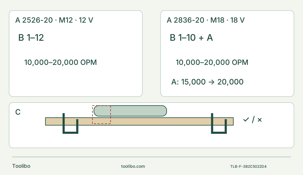
A · Qualify the entire power system
M12 and M18 are separate actual battery/charger prerequisites. Existing approved power can favor retention, but voltage alone proves neither access nor performance.
B · Choose a deliberate control mode
2526 has 1–12; 2836 has 1–10 plus moving Auto-Load. Equal nominal OPM ranges do not make dial numbers equivalent or A a safety stop.
C · Accept or reject the complete path
Check body, actual battery envelope, insulated grip, switch access, blade sweep, supports and exit with power removed. Only a qualified controlled sample supports the final choice.
Original schematic, not to scale. A and B are paired comparisons within the upper boxes, not separate performance tests. A on the M18 dial means Auto-Load, already moving at 15,000 OPM before load. C neutral tool shape is neither a measured body nor a promise that either actual battery/grip fits; its dashed region requires the complete real accessory envelope and underside clearance.
Choose the complete working space, not the voltage label
This comparison concerns the exact US Milwaukee 2526-20 M12 FUEL and 2836-20 M18 FUEL oscillating tools, under their May 2020 and June 2020 manuals respectively. The decision is which complete existing-owner system can make a visible, supported clean-wood cut with controllable access. It is not a claim that every 12 V tool reaches tighter places or every 18 V tool cuts faster.
Both manuals specify 10,000–20,000 OPM. That shared range does not establish equal cutting performance, vibration, runtime or battery demand. Nor does it reveal clearance around your actual battery, grip and blade. The useful output is a recorded choice—retain a qualified M12 setup, retain a qualified M18 setup, qualify an additional system, or reject both for the planned path—with a concrete reason for every unresolved requirement.
Use the matched manuals’ safety, assembly and operation sections, especially printed pages 3–5. This guide reuses their exact scope rather than pooling kit contents or assuming a later model revision. No separate battery/charger commissioning procedure is established here: each proposed system must already be approved under its actual battery and charger instructions.
Start with the same bounded job
Choose a manageable loose piece of known, uncoated solid softwood with a short marked straight cut, visible underside and adequate support. No installed cabinet, wall or hidden-service cut is included. Inspect the whole piece for embedded hardware and uncertain material. Mark the finished line, identify waste and decide how to support it through separation without closing the kerf.
Clamp the retained work to a stable platform and support the waste separately. Check every clamp and support against the full blade path. A tool that reaches the front of the line but strikes a clamp or loses hand clearance halfway through does not fit the job. Do not remove needed clamps simply to make a larger body fit.
For each candidate, identify a specifically recommended, sound wood-cutting accessory whose actual mounting and material approval you can verify. The generic blade drawings in the manuals do not identify every accessory sold in a kit. If that evidence is missing, record “accessory qualification pending”; do not fill the gap with an unmarked universal blade or a guessed catalog number.
Check access with power removed
Switch to OFF and remove the battery before fitting, adjusting or measuring around the accessory. Keep an actual battery’s dimensions available separately when considering the eventual assembled system; do not energize the tool or use it to probe an opening. Wear protective gloves for sharp cooled accessories and keep hands clear of their edges.
Compare the actual body, intended grip, blade orientation, full oscillating envelope and eventual battery envelope with the complete approach and withdrawal path. Allow a normal controlled hold and access to the OFF switch. A body fitting between obstacles while your fingers or the battery cannot clear them is not adequate access. Check below the stock and beyond the exit, not just above the marked line.
No numerical minimum clearance follows from this comparison. Measure the real systems, including the particular qualified packs, rather than scale a marketing photograph. If you cannot establish the assembled envelope without unsafe handling or missing dimensions, obtain reliable manufacturer information or a properly supervised demonstration; hold the purchase in the meantime. Do not run a blade to discover interference.
A change in blade angle may improve approach, but only through the documented isolated mounting sequence. It cannot turn a blade into a side-loaded pry bar or authorize an adapter outside the manual’s pictured interfaces. Recheck the entire path after every permitted angle change.
Both use a lever and a threaded bolt
These are not snap-in-only mounts: both bodies retain a threaded accessory bolt. For either, remove the battery, lift the quick-release lever and push it firmly forward over its detent. Turn the tool over, unscrew the accessory bolt and remove the old accessory. Clean dirt and debris from the bolt, flange and accessory.
Fit the appropriate accessory and original bolt, hand-tighten securely, then press the quick-release lever back into place. Confirm proper seating while isolated. If it does not fit snugly, do not force the lever or improvise spacers. Both manuals identify adapter 48-03-2526 for two particular pictured arbor profiles; those diagrams do not approve every brand or a cupped Starlock-only interface. This comparison’s simplest route is an identified recommended direct-fitting accessory. Any other route requires its own exact evidence.
Do not infer a numeric torque from “securely,” omit the bolt because the change is called tool-free, or transfer an adapter merely because it worked on the other body. A damaged holder, missing hardware or blade that cannot be secured ends the choice until qualified service or correct parts resolve it. Never use an energized wobble test to approve the mounting.
Controls are a real difference, not a speed ranking
The 2526-20 uses dial 1–12: 1 is 10,000 OPM and 12 is 20,000 OPM. Its manual does not provide a full per-number intermediate speed table, and it does not give this body the M18’s Auto-Load mode.
The 2836-20 offers manual positions 1–10 plus A. In A, it starts at 15,000 OPM and rises to 20,000 OPM when load is applied. It is already moving before contact: A is not a stopped standby, pressure-triggered safety feature or jam protection. Do not equate a number on its dial with the same number on the M12 dial.
Both have forward I for ON and rearward 0 for OFF, and both must come to full speed before work. Their cutting guidance specifies a high speed and controlled moderate pressure to avoid burning; it does not supply a universal exact starting number for all wood/blade combinations. For the worked trial, choose the documented manual-speed route and a controllable suitable setting; selecting A is a separate deliberate choice, never a substitute for checking access or controlling feed.
Two worked system decisions
Retain an already complete M12 setup. You own a commissioned M12 battery/charger system, have an identified recommended wood blade, and the isolated complete-envelope check passes the entire supported cut with a comfortable controlled grip. The 2526-20 is a defensible choice for this job. The existence of an M18 model is not evidence that you need another power system. If the M12’s actual pack or grip cannot clear an obstruction, however, its voltage label does not rescue it: change the setup safely or reject that path.
Retain M18 where access is genuinely adequate. You already have an approved commissioned M18 system and the exact 2836-20, blade, battery envelope and grip clear the full path. You understand the manual dial and the moving 15,000 OPM starting state of A. The M18 system can be selected without declaring it faster or safer than the M12. If a smaller-looking alternative is attractive, compare its actual entire system first; a bare body alone is not a complete purchase.
Neither system is complete. If you have only an unidentified pack, an unverified charger, unsupported blade or a path requiring a hand underneath the cut, stop. List the missing evidence and qualified components. Do not use a cross-platform battery adapter, infer compatibility from color or voltage, or buy a second tool before resolving workholding. A different method can be the right outcome when neither system permits a controlled complete cut.
Confirm the selected route on a sample
Proceed only with an undamaged already commissioned M12 system for the 2526-20, or M18 system for the 2836-20, under the actual supplied pack and charger instructions. There is no charging-light, duration or temperature recipe here. With OFF confirmed, slide the qualified battery into the body until it latches securely. The same press-release-buttons and pull-away action removes it; OFF alone is not isolation.
Wear ANSI Z87.1 eye protection and hearing protection. For dusty work, also use appropriate respiratory protection OR the manual’s OSHA-compliant dust extraction solution under the actual equipment instructions; extraction does not replace eye or hearing protection. This comparison establishes no hose attachment. Keep bystanders away, use stable footing, maintain a controlled insulated grip and keep hands away from cutting edges and from under the work. Inspect the blade before use; a dull or damaged blade can bind or kick back.
With the blade clear, start, allow full speed and make the short marked cut on the clamped sample with controlled pressure. Do not test a known obstruction under power. Stop if the work shifts, the blade binds, abnormal noise occurs or access becomes cramped. Switch OFF, wait for complete stop and remove the battery before investigating or changing anything. Do not use repeated restarts as evidence that one platform has “more power.”
After the cut, OFF, complete stop and battery removal precede inspection. Check the intended line, size, complete separation and surfaces for scorching or uncontrolled tearing; also confirm the supports stayed stable. A failed sample requires a specific safe correction or rejection, not a platform winner. If unexpected tool behavior persists, keep it isolated and seek authorized service rather than disassemble it.
Record the chosen body, actual power-system qualification, accessory, permitted angle, full-path clearance and sample result. The complete choice is the system that meets those conditions for this job—or no system yet. Similar OPM ranges and different battery labels cannot make that decision for you.
Models referenced