
Five-position control and the separate sanding inventory
Upper panel shows the 1–5 dial with cutting range 3–5 highlighted; lower panel identifies seven optional sanding dust components A–G, including felt ring, pad and holder bolt.
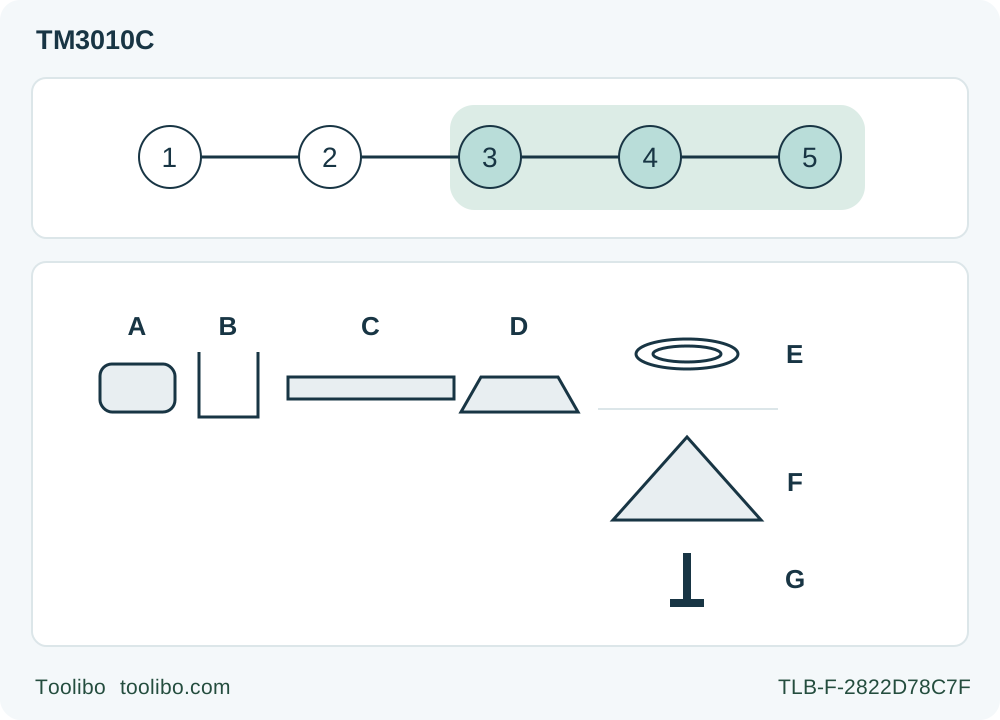
Cutting control · 1–5, preset 3–5
Move through intermediate positions; never force directly between endpoints. Select within the actual accessory instructions, start clear of the work and stop completely before withdrawing.
Separate sanding · complete A–G system
Unplug before installing joint, nozzle and attachment; engage the band protrusions in the body holes, fit felt ring and pad, fully seat the holder bolt and return the lever. Connect suitable extraction and align paper holes.
Original schematic. Top numbers are speed settings, not five installation steps. The lower shapes are an inventory, not dimensional assembly instructions: A joint, B nozzle band, C dust nozzle, D dust attachment, E felt ring, F sanding pad, G holder bolt. Follow the full unplugged assembly and do not infer saw-blade dust capture.
Match the corded body and its instructions
This is a complete loose-stock wood-cutting workflow for the US Makita TM3010C, matched to manual 885221-940 / TM3010C-1. The current TM3010CX1 product page links that manual, but a kit listing does not prove what is in an existing owner’s case. Identify the actual body, accessories and supplied instructions. This is the corded removable-holder-bolt system, not TM3000C or a cordless XMT model. No hands-on performance or current warranty claim is made.
The product identifies a 3 A motor; the operating manual gives 6,000–20,000 oscillations per minute and 1.6 degrees to each side. Read the actual nameplate voltage and frequency and use a matching supply. Do not infer overseas motor equivalence from the common model name or the extension-cord table’s separate voltage rows. This task uses a dry indoor bench and a directly reachable suitable outlet; it does not require charging or improvised plug adapters.
With the plug disconnected, inspect the cord, plug, strain relief, housing, switch, lock lever and holder. Damage, a switch that cannot reliably turn the tool off, binding parts or a cracked accessory require repair or replacement before work. Keep the cord clear of the entire blade path, waste and bench edges so it cannot be cut, snagged or pulled into the work. Never carry the tool by its cord or pull the cord to unplug it.
If an extension is genuinely needed, use the actual nameplate current and the manual’s complete cord table, not an arbitrary thin lead. For a confirmed 120 V, 3 A tool, its 0–6 A row gives minimum 18 AWG at 25 ft, 16 AWG at 50 or 100 ft, and 14 AWG at 150 ft. Smaller AWG numbers mean heavier conductors. The cord must be sound and appropriate for the environment. Do not treat these values as permission for damp work, a damaged outlet or an unverified circuit. Resolve electrical uncertainty before connecting. The manual requires GFCI protection where damp operation is unavoidable; this dry exercise excludes that situation rather than teaching wet operation.
Choose a known blade and a visible sample
Use a sharp, undamaged wood-cutting accessory specifically designed and recommended for this tool, positively identified from its instructions or manufacturer evidence. An accessory that physically attaches is not thereby safe or approved. Different installation sections require the correct optional adapter. Do not infer that the product’s broad adapter description permits every competing blade or Starlock tier; if the exact blade/adapter combination is unresolved, ask Makita and hold the project.
Choose clean, uncoated, loose softwood of a thickness within the actual blade’s usable reach. Inspect both faces and the intended cut path, removing nails rather than planning to cut them. Exclude hidden fasteners, services, unknown finish, treated material and embedded debris. Mark a short edge-start cut with the retained and waste portions clear. The blade must be able to finish without striking the bench, clamps, cord or anything behind the stock.
Clamp the retained piece to a stable support and support the waste against dropping or pinching the blade. Do not hold the piece against your body or in a free hand. Keep bystanders away, stand securely and arrange the cord so the whole intended motion remains unobstructed. Wear safety glasses or goggles, appropriate hearing protection and respiratory protection selected for the wood dust; ordinary spectacles are not safety glasses. Provide suitable ventilation and dust control. The tool is not waterproof: use neither water on the work nor a liquid-cooled accessory. These precautions follow the TM3010C manual’s safety instructions on pages 2–4.
Seat the holder bolt completely before closing the lever
Turn the switch to O and unplug before assembly or adjustment. A low dial setting or an OFF switch alone is not isolation. Allow previously used accessories to cool, protect against sharp edges and keep fingers out of the lever’s closing path: it can snap shut and pinch.
Open the lock lever fully and remove the holder bolt. Place the correctly oriented blade on the flange so its holes engage the flange protrusions. It may be indexed in 30-degree steps, but must not be upside down. Choose an angle that keeps the housing grip, cord and blade path clear. Insert the holder bolt all the way to its stop, then return the lever to its original position. Check secure seating while still unplugged. Do not substitute a threaded tightening routine, leave the bolt partly inserted or start with the lever open.
If the accessory rocks, the lever cannot return or the bolt will not seat fully, stop. Confirm identity, cleanliness and damage with the plug out; do not force the parts or energize the tool to “settle” them. A correct adapter, where explicitly required, belongs in its exact documented arrangement. An arbitrary ring, extra washer or borrowed bolt is not a solution. The installation and adapter figures are on manual page 6.
Select the actual five-position dial
The dial runs from 1 to 5, not the six-position scale on some cordless Makita bodies. Move through the intermediate positions; never force it directly from 1 to 5 or back. Higher numbers give a higher oscillation rate. For cutting, page 7 recommends presetting 3–5. Choose within the applicable blade/material instructions and qualify the setting on scrap, rather than inventing an exact frequency for each number.
Electronic constant-speed control is not permission to force the blade or ignore a stall. The prescribed cut should advance without unnecessarily slowing the accessory. Do not transfer another model’s restart protection, fault lamp or automatic recovery behaviour to this body; the matched manual does not establish those features here.
Complete the setup while unplugged, check that the switch is at O and the accessory is clear of the stock, then connect to the verified supply. Grip the housing firmly as instructed and do not touch the metal part. Keep the other hand safely away from the accessory and stock path; the work remains clamped, not hand-held. Slide toward I to start only with the tool controlled in its working position and the blade clear of contact.
Complete the cut, stop before withdrawing, then decide
Bring the running blade to the marked edge and advance with light, controlled guidance, keeping the cutting edge aligned. Do not force the tool toward a side that has no cutting edge. Do not twist or lever the blade to steer. Excessive pressure reduces efficiency and can stop the motor; reduce the demand rather than push harder.
The manual allows clearing sawdust by drawing the tool appropriately, but its specific safety rule governs removal from the work: switch OFF and wait for the blade to stop completely before withdrawing it. Use that sequence whenever a clearing withdrawal is needed. If the wood moves, the cord becomes threatened, the blade binds or control deteriorates, stop, wait, withdraw safely and unplug before correcting the setup. No powered fault or loose-mount test is included.
Finish the short cut without reaching into the waste path. Slide back to O, wait for complete stop before withdrawal or laying down, and unplug. The blade and stock may be hot; do not immediately touch them. Once safe to inspect, accept the sample only if the intended line and size are achieved, the cut breaks through as planned, and there is no uncontrolled tear-out, scorching or sign of shifted stock/support. Reject an unsuitable result and correct the isolated setup before another sample. No invented dimensional tolerance is implied.
A separate sanding route needs the whole dust stack
The lower diagram is an inventory of the optional sanding extraction system, not a saw-blade dust-capture claim. Before installing or removing it, switch OFF, wait for complete stop and unplug. Identify the joint, nozzle band, dust nozzle, dust attachment, felt ring, sanding pad and holder bolt. Do not omit the felt ring or replace it with a generic washer.
Install the joint, dust nozzle and dust attachment. Fit the nozzle band so its protrusions engage the holes in the tool. Put the felt ring and sanding pad on the dust attachment and secure them with the application-tool holder bolt using the complete lever/bolt procedure. Connect the vacuum hose to the dust attachment and use dust collection appropriate for the material. These are the page 7–8 sanding figures; they do not prove compatibility with another model’s latch assembly.
Fit the hook-and-loop sanding sheet in the pad’s direction and align the extraction holes. Reject worn or gritless sheets and never transfer paper previously used on metal to wood. For a separate small bare-wood sample, clamp it securely, select a suitable sanding setting by trial on scrap and keep the same grit until that surface is finished. The cutting recommendation 3–5 is not a universal sanding instruction. Start with the pad clear, work under control without excessive pressure, then end the pass, switch OFF, wait and unplug before inspection or paper changes. Accept only the intended even surface without unwanted rounded edges, gouging, scorch or movement. If the extraction system or required parts are incomplete, hold sanding even if the wood-cutting setup was successful.
Clean and store an unplugged system
With the plug out, remove the cooled accessory by reversing the mounting sequence and protect its cutting edges. Keep handles dry and free of grease, and clear dust from the tool without introducing liquid. Do not use gasoline, benzine, thinner, alcohol or similar cleaners, which can damage the housing.
The manual calls for periodic cleaning and lubrication of the lock lever’s moving part, but does not specify a lubricant here. Obtain the correct maintenance guidance rather than inventing an oil or flooding the mechanism. Repairs, carbon-brush inspection/replacement and internal adjustments belong with Makita authorized or factory service using proper parts. Persistent binding, damaged cord or unreliable switching is a service hold.
Store the clean, disconnected tool and identified accessories where children cannot reach them, with the cord protected from crushing and sharp edges. The completed owner outcome is a verified cut, a clear decision on whether the separate sanding system is ready, and an isolated tool—not a claim that every adapter, regional supply or illustrated kit component is interchangeable.
Models referenced