
Four separate systems behind the Cut icon
Four panels show neutral Easy-Lock engagement and final fastening, three separate control functions, the five bottom-to-top selector modes without numerical speeds, and three distinct flashing-error patterns.
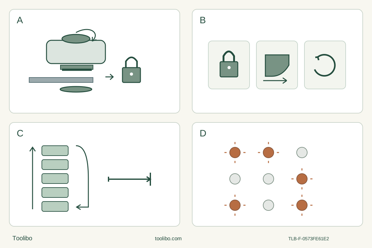
A · Isolate and complete the clamp
Remove the battery, loosen counterclockwise until the flange admits the accessory, engage all pins flush, then hand-tighten clockwise to the click without uncomfortable force.
B · Distinguish stopping from lock-on
Lock-off forward locks and backward unlocks. Trigger release stops unless lock-on is active; cancel by squeezing/releasing without lock-on, or pressing lock-on or the selector.
C · Preset the appropriate mode
Cycle Scrape, Grout, Sand, Cut, Max Range before operation. No mode changes while ON and no invented numerical mode speeds; use the qualified wood blade and medium initial entry.
D · Stop for the actual error pattern
Left/center flashing means overheated pack; right means excessive load and possible tool heat; left/right means incompatible or faulty pack. Isolate and follow the specific remedy, not forced restarting.
Original schematic. A does not count pins: all actual clamping pins must engage, with the accessory flush and the knob fully hand-tightened to its click; magnets alone do not clamp. B separates lock-off, variable trigger and lock-on. C shows mode order and a bounded range, not numerical bands. D colors only emphasize flashing positions, not actual LED colors or ordinary charge percentages.
This is an owner workflow with a real power-system prerequisite
The US MM12V combines an application selector with a variable trigger and a separate lock-on button. Choosing Cut does not identify the blade, clamp it, detect hidden services or make an unverified battery safe. This project ends with an inspected cut in a clean, visible softwood sample—not with selecting an icon.
Match the actual MM12V body and supplied operating instructions to document 1605A002FH, November 2024. The current US MM12V-S1 product links this manual, but its advertised 5,000–20,000 OPM range conflicts with the manual’s 7,000–20,000 OPM. This guide follows the matched dated manual and does not claim a supported 5,000 OPM setting or resolve the discrepancy by averaging. The manual identifies 10.8 V/12 V Max; a similar voltage on another battery is not compatibility evidence.
There is a further stop gate. Page 10 refers to a separate battery/charger list supplied with the tool; that list is not reproduced in the linked operating manual. Proceed only as an existing owner with the actual approved Dremel 12 V series battery and charger combination, its supplied list and complete instructions, already correctly commissioned. If that evidence is missing, obtain it from Dremel before operation. This article neither names an unverified pair nor teaches charging from an incomplete source. It does not extend the US accessory or power permissions to another region or platform.
Define the sample and remove the starting hazard
Use untreated loose softwood with both faces and the full cutting path visible. Mark the intended edge cut or notch and final dimensions. Exclude nails, screws, coatings, unknown embedded material and concealed building services. Choose an intact Dremel-specified wood-cutting accessory with instructions that approve the actual material and cut geometry. The Cut table includes MM100W, MM105W and MM150W among its examples, but the mode list alone is not proof that every listed blade suits every material. Check the actual blade’s identity and packaging before choosing it.
The US manual permits the Dremel oscillating accessory line, including U2, UTF and Universal Quick-Fit. It does not establish blanket cross-brand or Bosch Starlock compatibility. Max Range’s reference to any accessory remains inside the manual’s Dremel-specified accessory restriction.
Check the tool and pack for damage or modification. A cracked blade, uncertain holder, damaged pack or switch that cannot control the tool is a stop, not something to test under power. Keep loose metal away from battery terminals and do not open or repair a pack.
Release the trigger completely and ensure lock-on is not engaged. Before any assembly, adjustment or accessory change, press the battery’s release tabs and slide it completely out of the housing. The lock-off button is an additional control, not a substitute for removing the battery. Never insert a pack into a tool left locked ON.
Complete Easy-Lock rather than stopping at magnetic retention
Wear protective gloves for the sharp accessory and allow a used blade to cool. With the battery removed, turn the clamping knob counterclockwise. Continue loosening until the flange extends far enough to admit the actual accessory between flange and interface. Unlike the MM20V procedure, this manual does not tell you to push the knob to extend a spring-loaded flange; do not import that action.
Place the accessory so it engages all clamping pins and lies flush against the holder. An allowed angled orientation still requires full engagement and flush seating. The built-in magnets only hold the part temporarily while you secure it. They are not the final clamp.
Turn the knob clockwise fully by hand, stopping at the fully tightened audible click without applying uncomfortable force. Check the seated accessory and complete clamp before reinstalling power. Do not invent a numerical torque, add a wrench, accept a crooked blade or run a powered wobble test to discover whether it is secure. For removal, isolate again, loosen counterclockwise and lift the accessory off the pins; loosen farther if clearance is inadequate rather than forcing the blade.
Prepare support, protection and an unobstructed path
Clamp the sample to a stable platform. Support the retained piece and arrange waste so it cannot drop unexpectedly or pinch the blade. Leave clearance below and beyond the entire moving blade, not just its tip. Do not hold the work in your hand, against your body or with fingers hidden beneath it. If the geometry cannot be reached without touching a support or levering the blade, change the arrangement or choose a different method.
Use ANSI Z87.1 eye protection with front and side protection, hearing protection and appropriate dust protection for the material. Keep the area lit and ventilated, bystanders clear, and handles dry and clean. Both hands must hold the tool firmly on its proper gripping areas, with fingers out of the cut and vents unobstructed. A source illustration showing one hand does not override the repeated two-hand instruction. Keep footing and balance; do not reach across the cutting path.
This clean sample does not authorize sanding old paint, working wet, opening installed walls or cutting unknown services. Dust protection and an application icon cannot turn an unidentified material into a suitable sample.
Understand all three controls before the cut
The lock-off button moves backward to unlock the trigger and forward to lock it for storage or transport. With the trigger fully released and lock-on disengaged, slide the qualified charged battery into the housing until it locks. Keep the accessory clear while arranging the control setting.
Press the application-selector button before operation. Its five modes cycle from bottom to top: Scrape, Grout, Sand, Cut, Max Range, then back to Scrape. Select Cut for this qualified wood task. The mode cannot change while the tool is ON. The manual provides no numerical speed band for each mode, so do not assign invented OPM values to the five icons or treat their order as a five-speed dial.
After unlocking, squeezing the trigger starts the tool; trigger pressure changes speed within the selected mode’s permitted range. Releasing it normally stops the tool. The LED work light comes on with trigger operation, but it is not an isolation indicator. Do not repeatedly pulse ON and OFF while cutting.
Lock-on is the important exception to “release to stop.” The manual’s engagement sequence is full trigger pressure, press lock-on, then release the trigger. To cancel it, squeeze and release the trigger without pressing lock-on; alternatively press the lock-on button or application-selector button. The selector’s cancellation function is not permission to change modes while running. This short sample uses ordinary trigger control, not continuous lock-on, but you must understand cancellation before starting and must never leave the trigger locked ON for insertion or storage.
Make controlled passes, then accept or reject the result
Practise on matching scrap first. The manual calls for medium speed at the initial plunge for control, with a possible increase after the initial cut. That is qualitative guidance, not an exact trigger percentage or a hidden numeric Cut setting. Let the tool reach the selected operating speed before contact, then lower the blade lightly onto the starting point.
Guide it with a smooth back-and-forth motion, removing a little material on successive passes until the required cut is complete. Maintain two-hand control and the support arrangement. Do not force or twist the blade: twisting can bind it, and pressure is not a substitute for the correct sharp accessory. The manual’s full-speed-before-contact instruction means the selected operating condition, not an instruction to use the maximum range on every cut.
For an ordinary completed pass, remove the tool from the work before switching off, as this manual directs. Release the trigger—or cancel lock-on if it was inadvertently engaged—then wait for complete stop. Lay the tool down securely; do not stand it on its battery. Remove the battery before touching the blade, clearing waste or inspecting the sample. Allow the blade to cool.
Accept the sample only when the intended line and size are achieved, the required cut is complete, and there is no uncontrolled tear-out, scorching or evidence of shifted support. Use the sample’s actual requirements rather than an invented tolerance. A wandered line or shifted clamp means reject the setup and correct it before another isolated remount or trial. A successful bench sample does not approve an installed or blind cut.
Read charge and error signals as different information
The ordinary charge display shows three lit LEDs for 75–100%, two for 40–75%, one for 15–40%, and one blinking for less than 15%. Those indications are not a capacity test, authentication check or proof that a pack is undamaged.
The troubleshooting chart gives separate flashing patterns, viewed in the orientation of the actual display: left and center means an overheated battery; right means excessive pressure/load and possible tool overheating; left and right means an incompatible or malfunctioning battery. The diagram’s colored emphasis is not a claim about the physical LED color.
Stop for these indications or for unexpected vibration, binding, smoke, unusual heat or a loose accessory. Release/cancel the running control, wait for stop and isolate before inspection. Let an overheated tool and pack cool as instructed; correct excessive pressure and load rather than forcing a restart. An incompatible or faulty pack requires the correct approved replacement route, not an adapter or battery repair. Persistent unexplained problems go to Dremel service. No flashing error is not a general safety certificate.
Close the task without expanding its permissions
Sanding requires its own approved pad, fitted matching sheet and material assessment. With the battery removed, align and hand-press the hook-and-loop sheet onto the pad. The manual describes a specific brief powered adhesion-seating step against a flat surface after assembly; this is not permission to change sheets while powered or begin a normal cut in contact with the work. Any sheet replacement or pad rotation requires stopping and removing the battery again. Do not infer an extraction system or hazardous-finish procedure from the Cut setup.
After this wood project, engage lock-off forward and remove the battery. Keep vents and controls clean without inserting pointed objects, and avoid solvents that damage plastic. There are no user-serviceable internal parts. Store the tool and removed pack on a clean, dry, uncluttered, preferably noncombustible surface within the matched temperature requirements. The tool’s ambient storage range is −20 to +50°C; the actual battery instructions can impose additional restrictions. Charging temperatures and procedures must come from the qualified complete system, not from guessing at the missing list.
Source basis: MM12V Operating/Safety Instructions 1605A002FH, November 2024, English pages 2–25, especially specifications 10, assembly 11–13, controls 14–18, accessory limits 19, cutting 20/23 and troubleshooting 24; current exact US product/manual link. The speed discrepancy and absent separate power list remain explicit qualification limits.
Models referenced