
Four exact-system recognition gates
A identifies WX531L 6900/min scope. B distinguishes depth lever 17 and front bevel lever 12. C shows designated handle 3/safety 1/trigger 2 with detached power. D connects original outlet 13/adapter 14 to extraction.
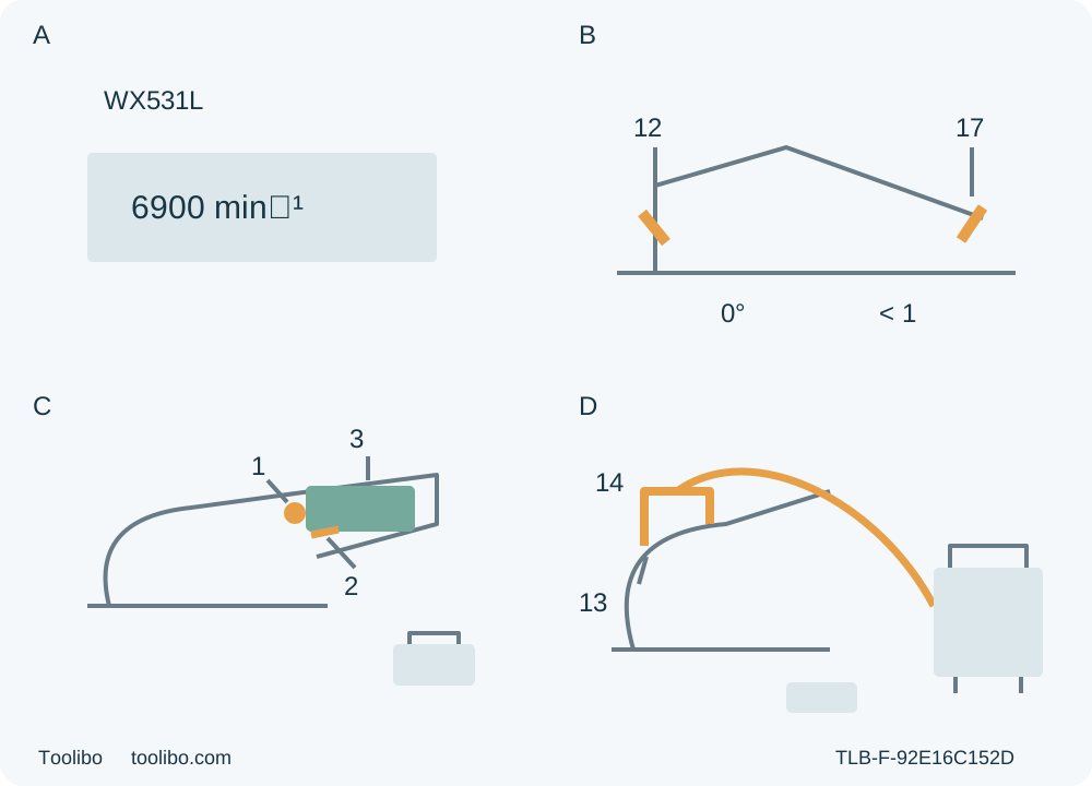
A · Match actual 6900 and original blade
Physical WX531L/AR01474500 and original rated WA5043 must match; conflicting 6100/2100 units are not silently included.
B · Separate depth and bevel
Battery-out lever 17 follows F1/F2; front lever 12 locks zero. Verify through-cut, less than full tooth and all support/guard clearances.
C · Use only the designated grip
Handle 3, safety 1 then held trigger 2; free hand clear, no stock holding or invented auxiliary grip. Actual full stop before withdrawal.
D · Qualify complete active capture
Original outlet 13/adapter 14/hose/extractor system already qualified; isolated connection checks and actual operation before the cut, no guessed diameter.
Original isolated recognition, not to scale or a live-cut demonstration. A is the actual physical/document applicability gate, not a correction of conflicting current product speeds. B requires real less-than-full-tooth breakthrough and locked zero. C marks only the designated handle; no second grip is invented, and the free hand stays away from stock, waste, base and cutting area. D requires complete already qualified native hardware and active suitable extraction; connection checks are battery-out with extractor isolated. No fitting, charging or advertised brake-time guarantee.
A current WX531L product name is not enough to establish which operating instructions apply to the saw in your hand. The AR01474500 manual specifies 6900/min, while the current US product page gives 6100 RPM and also a separate 2100 RPM field. This guide does not reconcile those numbers. It applies only to a positively matched actual 6900/min WX531L, its supplied AR01474500 instructions and the original qualified wood-cutting system.
A differently marked, altered or uncertain unit is a HOLD for manufacturer clarification before cutting. The manual’s copyright is 2020; that is not a claim that every current carton contains that revision. WX531L.X and .9 package naming does not create another mechanical body or authorize pooling newer included batteries with the older operating table.
The complete outcome here is one modest, supported, edge-to-edge square crosscut in known dry loose wood, followed by stopped, isolated inspection of both cut faces and the tool setup. It is not a plunge-cut, blade-fitting or new-battery commissioning lesson.
1. Qualify the original blade, power and dust system
The existing original 24-tooth TCT wood blade must be positively identified as WA5043, with its documented 4½-inch diameter and 3/8-inch bore, and correctly installed with the original inner flange, outer flange and bolt. Its marked speed must be at least the speed marked on the actual tool. For the 6900/min body admitted here, that means at least 6900/min on the qualified blade; the conflicting 6100 product number cannot lower the requirement.
Unknown blade approval or rating, a substituted bore, loose hardware, damaged teeth or doubtful flange assembly means HOLD. Do not infer qualification from diameter alone or from the fact that the saw runs. Inspect the isolated original blade for dullness, damage and deposits, and accessible tool parts for breakage, binding, misalignment, a bent base or loose fasteners. No blade replacement, flange-face selection, spindle-lock procedure, bolt direction, torque or chemical sharpening/cleaning recipe is supplied here.
Use only the actual already-commissioned WA3575 battery and WA3881 charger under their own complete instructions. Both appear in the AR01474500 table, but this guide does not newly commission or charge them. The current product’s WA3669 package listing is not approval to substitute it into this document-scoped workflow. The manual describes 20 V maximum and 18 V nominal; matching a voltage label or PowerShare branding alone is insufficient.
Damaged, modified, leaking or mechanically shocked power components require a hold under their actual instructions. Do not open packs, short terminals or attempt service. Keep them clean, dry and away from heat, fire and metal objects that could bridge terminals. The manual’s use and storage range for tool and battery is 0–45°C. That is distinct from the stated charging-system range and is not a charging tutorial.
The complete native adapter 14 and outlet 13, actual compatible hose and suitable extractor must already be correctly qualified. The operating table expressly requires the adapter to stay connected to a dust-collecting device during use. A later troubleshooting suggestion to “consider” a vacuum does not make capture optional here. Missing, uncertain or ineffective extraction means HOLD before the sample.
No hose diameter, airflow or vacuum threshold is established by this manual. Qualify the actual extractor for the material and exposure conditions under its own instructions, rather than borrowing a Bosch threshold or taping on a hose. This guide does not install or substitute an adapter. Keep the hose clear of the designated grip, base, blade, guard, clamps and supported exit, without sideways pull.
2. Remove power and inspect the guard
Release the trigger and wait for complete blade standstill. Then press the battery release and slide the pack outward along its actual rear rails until completely removed, as A1 shows. The safety switch is not physical isolation. Battery removal precedes guard checks, depth and bevel settings, guide work, hose connection, maintenance and storage. Isolate the extractor under its own instructions before checking connections.
Before each use, check free lower-guard movement, immediate full closure and correct spring operation. Use only the retracting handle for the isolated check, with fingers away from teeth and pinch points. It must not touch the blade or any other part at all angles and depths of cut. Recheck after a drop; a bent, sticky, damaged, intermittent or slow guard needs service before use. Never tie or clamp it open.
The ordinary edge-entry cut uses automatic lower-guard operation. Do not transplant the manual’s separate plunge illustrations into this workflow or hold the guard open while advancing. Confirm the actual selected depth and zero setting again after adjustment, without replacing the full-range inspection.
With power removed, check that the safety switch and trigger are intact and unobstructed. A known failure to control ON/OFF, unexplained vibration, looseness or other defect requires qualified correction, not a powered fault test. Remove the hex key and other setup tools before connecting the battery. Keep the designated soft-grip handle clean, dry and free from oil or grease.
3. Qualify the one-handle working envelope
Handle 3 is the designated soft grip in the component list and actual ordinary-cut figures. Those figures show control from that handle; no auxiliary handle or approved second motor-housing grip is identified. The general safety sentence says that if both hands hold a saw they cannot be cut, but it does not supply a second gripping location on this model. Do not invent one on the upper guard, motor, base or dust adapter.
Use only the designated handle for this source-matched operation, and keep the other hand completely clear of the cutting area, blade, base and underside of the work. It must never hold the stock, steady the waste or catch the offcut. This is not a claim that every one-handed setup is controllable. If the actual supplied instructions or physical markings conflict, or the entire path cannot be controlled from the documented grip, HOLD for exact qualified clarification or a different cutting arrangement.
Choose clean, dry, new, uncoated wood of known identity that is suitable for the original TCT blade. Inspect the route for nails, screws and other foreign material. Exclude installed construction, hidden services, damaged or unstable stock, metal, tile, abrasives and plastic. The manual contains abrasive warnings and accessory symbols despite a no-abrasive rule, and a plastic symbol despite an explicit plastic prohibition. None authorizes those materials in this wood-only workflow.
Use a dry, clean, well-lit workspace without flammable liquids, gases, explosive dust or bystanders in the working area. Maintain stable footing, secure hair and loose clothing, and do not reach beyond balance. Wear eye, hearing and dust protection, with protective gloves as shown in the model’s operating figures; PPE must fit and not introduce loose material near moving parts. Use suitable dust-mask/respiratory protection and ventilation for the actual exposure. The small blade and short task are not exposure exemptions.
Clamp retained stock securely to a stable platform, supporting the work near the cut and outer edges as needed. Independently support waste while allowing it to separate without closing or pinching the kerf. Supports and clamps must stay clear of the blade below the stock. Keep the base on supported retained material, not a piece that will become unsupported at separation.
Before power connection, verify the entire entry, middle and exit route: stable base support, designated grip and safe stance, free guard movement, retained work clamped, waste supported, and hose free of snags. Check reach beside or safely above the route with blade guarded and no tooth contact; do not push an exposed blade through uncut stock as a rehearsal. If finishing would require a hand under the work or on the offcut, the task is not ready.
4. Lock actual depth and zero
Keep the battery out. Identify depth-adjustment lever 17 on the motor side, following the actual F1/F2 unlock and lock directions rather than copying another saw’s UP/DOWN rule. Release the lever, adjust the base/body relationship to the actual stock, and relock securely. Verify real breakthrough while strictly less than a full tooth projects below the wood, with clear space for the blade beneath. A deep illustrative drawing or nominal scale setting does not override the safety limit.
The front bevel-adjustment lever is 12. Release it, set the base square at the actual zero position and lock it securely. Check that both depth and angle remain fixed and that the guard and hose remain clear. An uncertain original alignment or a lock that does not hold is a service hold; no calibration screw or high-angle procedure is supplied.
For this square cut, use the actual zero-degree cutting mark 9 shown in D1/D2, not mark 10 for 45 degrees. Do not guess a left/right notch assignment from another WORX model or use a factory-offset number invented from the picture. Establish the actual intended cut relationship on equally safe supported material and inspect after stop and isolation if dimensional fit matters.
If the original parallel guide is the already qualified guide for the actual layout, its fit and clamping fixture 11 must be sound under the matched E1 instructions, and the setup key removed before power connection. It must follow a reliable edge without forcing the blade or colliding with a clamp. This crosscut does not require inventing a guide arrangement merely because the accessory exists. Any proposed guide or straightedge must preserve the full base, grip, guard, hose and waste clearances already required; otherwise HOLD.
5. Establish active capture and make the cut
With saw and extractor isolated, check the existing complete native connection and full hose route. Then activate and check the qualified extractor under its own instructions before cutting; an idle connected hose does not meet the active-capture prerequisite. Do not treat missing visible dust as proof that exposure is controlled.
Confirm the trigger is released, safety switch intact, settings locked and key removed. Refit only the already qualified battery along the actual rails to full secure seating as A3 shows. Do not force a doubtful pack or use power to investigate an unexplained fit. Keep the free hand out of the cutting envelope throughout handling and operation.
Grip handle 3 firmly by its insulated gripping surface, with the body to either side rather than directly in the blade plane. Place the front base stably on supported retained stock with the blade clear. Press safety switch 1, then pull and hold trigger 2. Let the blade attain full speed before contacting the wood. Advance smoothly forward, keeping the base stable and the ordinary guard automatic. Do not force a slowing blade, twist to recover a line, hold the guard open or release control to move a hose.
After the cut is complete, release the trigger and keep the tool stable until the blade has actually stopped. Do not lift or withdraw a moving blade. Confirm the guard covers the blade before safe setdown, then remove the battery completely and let hot blade and cut edges cool before inspection. Current advertising about an immediate electronic brake does not supply a guaranteed stopping time or replace actual standstill. No LED operating sequence or readiness signal is inferred from marketing.
If the blade binds or the cut is interrupted, release the trigger immediately and hold the saw motionless in the material until complete stop. Never pull a moving blade backward or lift it from a trapped kerf. Isolate and establish the cause and qualified correction before further work. There is no in-kerf restart, forced escape, automatic reset or powered diagnostic procedure in this guide.
6. Finish with a documented acceptance or hold
After isolation and cooling, inspect complete separation, the intended line, end squareness, size and both faces. Check for tear-out, scorching, a broken-off end or an uncut bridge. Verify that settings, clamping, guard movement, grip access and extraction remained satisfactory. Acceptance requires both a suitable result and normal system behaviour, not merely a cut piece. No nominal 2×-lumber claim certifies the actual stock, support or finish.
Unexplained slipping, vibration, failure to start, binding or repeated poor tracking means HOLD. Do not repeat the manual’s anomalous cordless troubleshooting references to a working mains outlet or carbon-brush replacement as an owner procedure. Nor does a troubleshooting blade-remount suggestion expand this original-assembly scope. Qualified service or exact manufacturer clarification must resolve doubtful condition.
Remove the battery for external care. Keep the guard, base, ventilation slots and controls free of dust using the manual’s dry-cloth approach, without water, chemical cleaners or added lubrication. No internal user-serviceable work is taught. Store tool and battery dry within the stated 0–45°C range, retaining their exact instructions and the sample’s acceptance record. A future change of blade, pack, adapter or supplied document requires renewed qualification rather than silent reuse of this result.
Models referenced