
Four WX429L checks before a wood sample
Panels show the original 115 mm 24T blade with a 9.5 mm bore rather than 10 mm; rearward safety control then upward trigger squeeze; isolated front bevel 11 and rear depth 16; and a stationary blade-left supported layout with rear-grip contact, separate hose and cord.
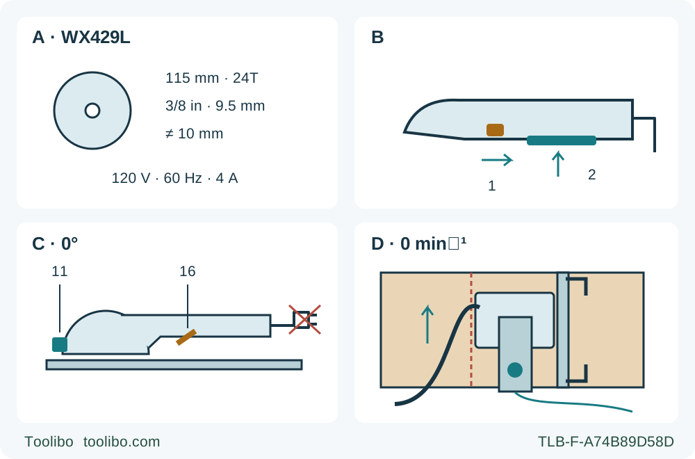
A · Exact blade and supply
Match the original 115 mm, 24T TCT blade with 3/8 in / 9.5 mm bore, not 10 mm, and the actual 120 V/60 Hz/4 A supply label.
B · Start sequence
Recognize the rearward safety action followed by trigger squeeze; unplugging, not the safety switch, isolates the saw.
C · Separate settings
Set zero at front bevel lever 11 and lock rear depth lever 16 with less than a full tooth below the wood.
D · Supported isolated layout
Clamp the retained work, use the designated rear grip and connect suitable extraction with the hose and cable clear.
A qualifies the original wood assembly, not a replacement recommendation. B is a side-view control sequence: move safety control 1 toward the rear/cord end, then squeeze trigger 2; neither action isolates power. C identifies front bevel lever 11 and rear depth lever 16 while unplugged. D is a disconnected, stationary planning view: upward intended travel, blade left and broad retained support right. The single dot is the original rear grip, not an added handle; the free hand never holds the stock. Hose and cord remain clear of the guard and travel.
Keep this compact saw’s workflow model-specific
The WORX WX429L combines a rear soft-grip handle, a safety-switch/trigger sequence, a rear depth lever and a front bevel lever in a compact corded body. It does not acquire a large saw’s auxiliary handle just because a general warning mentions two-hand protection. This guide follows the actual operating illustrations and controls in WORX manual AR01295003 for an existing US WX429L.
The outcome is a supported square wood sample with the original correctly fitted 24-tooth TCT blade, connected dust extraction and a checked guide setting. The current official product page directly links this manual. The booklet carries a 2019 copyright; a later PDF modification timestamp is not treated as a new printed revision. Read the complete instructions and compare the actual model, controls and supply label before following the workflow.
Material scope is deliberately narrow. The current product marketing mentions materials beyond wood, but the manual explicitly says not to cut plastics. The same manual also contains abrasive-cutting material alongside a warning not to use abrasive wheels. This guide does not resolve those conflicts by selecting the more permissive passage. It uses known untreated wood with the correct original wood blade only, and excludes plastic, metal, tile, abrasive wheels and internal plunge cuts.
Confirm the installed assembly, not just the blade diameter
Unplug before inspection or adjustment. The documented US supply is 120 V, 60 Hz, 4.0 A, and the no-load speed is 3,500 rpm. The wood-blade entry is 115 mm / 4-1/2 in, 24 teeth, with a 3/8 in bore given as 9.5 mm. That is not the 10 mm bore used by some other compact saws. Do not force a similar-looking blade onto the spindle or use an improvised adapter.
Start only with the approved original blade, inner flange, outer flange and bolt correctly fitted in the intended orientation. The blade must be undamaged, suitable for the wood and rated at least as fast as the tool’s marked speed. Blade diameter, tooth count or a seller’s compatible-products list alone cannot establish the whole mounting arrangement.
If the blade has been changed or the installation is uncertain, stop and use the complete model-specific Figure A instructions or qualified service before proceeding. This guide does not supply an invented bolt torque, transfer another saw’s thread direction or present a partial fitting recipe. A slipping blade is a fault requiring correction, not a reason to push harder or tighten blindly.
Inspect the rear grip, base, cord, plug, levers and visible fasteners. Check the lower guard with the saw disconnected: it must move freely and close immediately without contacting the blade or another part at all angles and depths of cut. The spring must work properly. A damaged, slow or nonclosing guard stops use. Never clamp or tie it open; the ordinary cut here relies on automatic guard movement.
Establish the electrical and dust connections
Use a matching supply and an undamaged cord and plug. Do not modify the plug or use an unsuitable adapter to make a mismatch fit. Route the cable away from the blade, sharp edges, heat and snag points. If an extension is necessary, it must be properly rated for the tool and environment; a loose or damaged connection is not a workable compromise. Keep the work area dry, well lit and clear of bystanders.
The operating table specifically instructs keeping the dust adapter connected to a dust-collecting device during use. A later troubleshooting suggestion to “consider” a vacuum does not cancel that operating requirement. With the saw unplugged, fit the correct adapter to the extraction outlet and connect a suitable dust-collection hose as shown in Figure H. Do not invent a universal hose diameter or make the adapter alone stand in for an extractor.
Check the hose through the entire travel: it must not block the lower guard, pull the saw sideways or snag on the work. Keep hose and power cord distinct and controlled. Use suitable eye, hearing and dust protection and ventilation for the selected wood. Unknown coatings or chemically treated/reclaimed material do not belong in this introductory sample. Extraction reduces airborne debris; it does not excuse poor housekeeping or inadequate protection.
Arrange support around the retained piece
Choose a board large enough to support the base and secure it to a stable platform. Mark the retained dimension and the waste side using a reliable square. Keep the base on supported retained material as the offcut separates, and leave the blade’s full path clear beneath the board. Do not clamp the waste so that the kerf closes on the blade or arrange the cut so the remaining board tips at the finish.
For a larger panel, support both sides near the cut and near the outer edges to avoid sagging. This is different from simply placing two supports far from the cut line. Keep all clamp heads, screws and bench parts outside the blade and housing paths. Very small pieces requiring a free hand to hold them are unsuitable for this workflow.
The model’s operating Figures C1/C2 show use of its designated rear handle. Grip that handle firmly and keep the body to one side of the blade’s line. Do not invent a front auxiliary handle, grab the guard or use the free hand to hold the stock. Neither hand belongs beneath the work or near the cut. If the real layout cannot be controlled with the specified grip while the work remains independently secure, change the layout or obtain practical instruction rather than improvising.
Set depth, zero bevel and the guide separately
While unplugged, release the rear depth-adjustment lever 16. Set the depth for the actual board thickness, then lock the lever as shown in Figures E1/E2. Less than a full blade tooth should be visible below the work. Check the real projection, not just the marked scale or the tool’s maximum 43 mm square-cut capacity. Maximum capacity is not a recommended setting for a thin sample.
Use the front bevel-adjustment lever 11 to establish zero bevel, then lock it securely. Do not confuse this front angle control with the rear depth lever or the nearby guide clamp. The tool can tilt to 45°, but this sample stays square. A zero mark that produces a nonsquare result is a reason to stop and check the setup, not to start an unplanned base-calibration procedure from Figure I.
For a rip parallel to a straight board edge, insert the matching parallel guide through the base and secure its clamping fixture with the hex key, following Figures D1/D2. Check that the guide follows a straight reference and cannot shift. If using a separately clamped straightedge, measure and test the actual base-edge-to-cut offset; do not assume that the narrow body shares another compact saw’s offset.
Use the 0° alignment mark for the square cut, not the 45° mark. Make a disposable sample to establish where the installed blade removes material relative to that reference. Keep the kerf on the waste side of the intended finished boundary. Confirm that the chosen guide and all clamps leave room for the rear handle, cord, hose and guard throughout the cut.
Recognize the switch before connecting power
The safety switch 1 must be operated before the on/off trigger 2. In the manual’s side view, the first action moves the safety control rearward toward the handle/cord end, followed by squeezing the trigger upward into the handle. The original illustration’s arrows describe that sequence, not feed direction.
Check the controls while unplugged, with fingers clear of the blade. A switch that will not reliably control the tool requires repair; it is not acceptable to bypass the safety control. The two-action start reduces unintended operation but leaves the saw electrically connected. Unplugging remains mandatory for setup, blade work, maintenance and storage.
Rehearse the approach and clearance with power disconnected. The diagram’s D panel is also an isolated, stationary layout: upward intended travel puts this model’s blade on the left, with the broader base support to the right. The single dot marks the original rear grip. It is not a suggestion to add a second handle or place a free hand on the board. The hose and cord should remain separate and clear throughout the movement.
Cut, stop and evaluate the result
Connect power only after the work, guide, depth, angle and extraction arrangement are ready and the trigger is released. Place the front of the base on the work with the blade clear of the entry edge. Operate the safety control and trigger, allow full speed before entering the wood, then advance smoothly forward with the base flat and the guide following its reference. Do not force the saw or twist the blade back onto a missed line.
If the blade binds or you must interrupt the cut, release the trigger and hold the saw motionless until the blade stops completely. Never pull a moving blade backward out of the kerf. Unplug before investigating support, depth, guide alignment, blade condition or debris. A restart in an existing kerf requires the blade centred with its teeth disengaged; do not restart against a trapped blade or an uncorrected cause.
At the normal finish, maintain control and support, release the trigger and wait for complete standstill. Confirm that the lower guard covers the blade before setting the tool down. Do not touch the hot blade or reach for the offcut while anything is moving. This guide makes no brake or fixed stopping-time claim.
After disconnection, measure the retained dimension, check the edge with a square and inspect whether the guide, clamps and support stayed put. A straight-looking cut does not excuse a slipped clamp or a damaged guard. Correct the isolated setup and repeat a sample if necessary. Persistent slipping, erratic cutting, vibration or electrical trouble belongs with qualified service, not repeated forced trials.
Clear accessible dust and chips from the guard, base and ventilation slots with the tool unplugged. The manual specifies a dry cloth, not water or chemical cleaners, and says the tool needs no additional lubrication or user-serviceable internal maintenance. Keep it dry in storage, and have a damaged cable replaced through the specified qualified route. Record the accepted stock, depth and guide arrangement so the next cut begins from a verified setup.
Models referenced