
Four controls that must agree before the sample
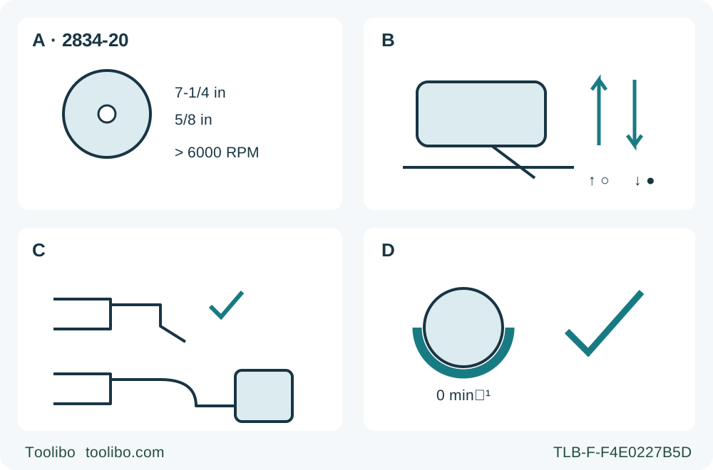
A identifies 2834-20, 7¼ in blade and 5/8 in bore, with blade speed rating above 6,000 rpm. B shows the depth lever loosening upward toward the motor and locking downward. C shows the dust chute as one allowed option and a connected vacuum adapter as the other. D requires zero rotation and lower-guard coverage before setdown.
A · Qualify the installed wood assembly
Match the actual 2834-20 and original 7¼ in / 5/8 in system; the blade rating must be greater than the marked no-load speed.
B · Isolate and lock depth
Remove the battery, push lever 18 up toward the motor to loosen and down to secure; also lock the separate zero-bevel knob.
C · Complete the discharge system
Use the chute or an adapter secured by its screw and connected to a vacuum; route the hose clear of guard and travel.
D · Wait for the real stop
Release the trigger, wait for complete standstill before removing the saw from the work, and verify guard coverage before setdown.
All setup checks are performed with the battery removed. A gives blade qualification, not assembly instructions; the permitted blade speed must exceed the actual nameplate no-load speed. B concerns lever 18 only, not a depth-detent recipe, and both the less-than-full-tooth rule and the stated projection ceiling still apply. C accepts either a correctly fitted chute or the secured adapter with a connected vacuum; a bare outlet and an unconnected adapter are not alternatives. This sample uses the vacuum arrangement. D requires actual standstill and guard coverage, never a fixed two-second wait. The panels contain no running-cut handedness or restart instruction.
The Milwaukee 2834-20 combines a powerful M18 drive with familiar-looking controls, but its guard check, depth lever and discharge arrangements deserve model-specific attention. A depth detent is not a locked setup, a dust opening is not an acceptable bare outlet, and an electric brake is not permission to lift a still-moving blade. This owner workflow brings those checks together in one supported, edge-start square wood cut.
Use it only with the actual US 2834-20 matching operator manual 58-14-0586, footer 58140586d4 / 961014925-04(A), dated 12/24. The manufacturer’s current product information links that manual and identifies the same body. Read the complete owner instructions, and stop if the nameplate, controls or supplied document do not match. No kit variant or battery capacity is counted as a different saw here.
Qualify the original assembly and commissioned power system
The manual identifies an 18 V M18 saw with a 7¼ in blade, 5/8 in arbor and 6,000 rpm no-load speed. Its maximum listed depth is 2⅝ in at a square cut and 2 in at 45 degrees. This exercise uses a manageable piece well within the actual configuration’s capacity, not a maximum-depth demonstration.
The existing original wood blade, inner flange, outer flange and bolt must already be correctly assembled and in sound condition. The blade’s maximum safe operating speed must be greater than the no-load speed marked on the actual nameplate. Do not weaken that instruction to equality. Check suitability for the selected wood, tooth condition, blade identity and the correct installation record. A crack, missing tooth, unsuitable blade or uncertain flange arrangement stops the task.
The manual uses the OFF direction marked on the blade flange to identify removal. Do not import a thread-direction rule from another brand or turn that marking into a partial fitting tutorial. The inner flange’s orientation and matched outer hardware matter; this guide does not ask the owner to dismantle them, change the blade or guess a torque. Do not use abrasive cut-off wheels or dry diamond blades. The present workflow excludes metal, plastic and plunge cutting even where the wider manual discusses additional applications.
The power prerequisite is an already commissioned genuine M18 battery with the exact charger specified for that battery, under both complete owner manuals. The product’s M18 compatibility statement does not supply an unidentified charger’s mains requirements, charging sequence or fault-light meanings. This article does not select a new pair, promise a kit or teach charging. Use a ready, undamaged pack whose actual approval and normal condition are established; an uncertain or modified power system is a stop condition.
The saw’s recommended ambient operating range is 0–125 °F. That is not a charging-temperature permission: the actual battery and charger limits still control their use. Protect detached terminals from conductive objects, do not expose packs to heat or fire, and do not use damaged or modified packs. Release and lock the trigger before handling the pack, and keep fingers away from the trigger during insertion.
Make the guard check in the specified position
Remove the battery before inspecting or adjusting the tool. Press its release buttons and pull it away; do not rely on the trigger lock as setup isolation. Keep the pack detached throughout the guard check, depth and bevel setting, guide positioning and discharge fitting.
The manual’s lower-guard check is position-specific. Rest the saw on its side; it says the check will not show proper operation otherwise. With the assembly stationary and hands clear of the teeth, grasp the lower guard at its sides, push it fully back into the housing and release it. It must spring back immediately. Before each use, with the battery removed, also check free guard movement without contact against the blade or other parts at all angles and depths of cut. This is an isolated inspection, not permission to hold the guard open during a cut.
If debris interferes, remove chips and debris from the upper and lower guard areas with the battery out, then repeat the check from the beginning. If immediate return is still absent, stop and obtain authorized service. Damaged guard parts, a faulty spring or a bent component are not solved by tying the guard open. After a drop, confirm clearance at all angles and depths of cut. The guard should operate automatically during this ordinary edge-entry sample.
Check the shoe, handles, trigger and visible fasteners as well. Loose parts, unusual noise, binding or a switch that cannot reliably control the tool require correction before use. Keep the handles dry and free of oil. Neither an LED nor a working brake compensates for a faulty guard or insecure shoe.
Choose a complete discharge arrangement
The manual requires either the dust chute or the vacuum-hose adapter connected to a vacuum. Running with neither fitted is not an acceptable third option: thrown dust or foreign objects can reach the face and eyes. The two approved arrangements should not be confused with a bare port or an unconnected adapter.
For this sample, choose the connected-vacuum arrangement appropriate to the wood and workplace. With the battery removed, insert the matching adapter into the upper guard and tighten its screw securely. Connect the vacuum hose and twist the joint to secure it, following the extraction equipment’s instructions. Check that the hose cannot pull on the tool, interfere with the lower guard or catch a clamp over the whole travel. Do not borrow another saw’s adapter, hose specification or minimum suction number.
Wear eye protection marked ANSI Z87.1, and arrange hearing protection and suitable ventilation. The manual requires an OSHA-compliant extraction solution used according to its instructions or appropriate respiratory protection in dusty conditions; assess the material and exposure rather than assuming a hose removes every hazard. Use additional respiratory protection where the assessment requires it. Unknown treated wood, lead coatings and asbestos-containing material are outside this sample. Do not use cutting oil or work near flammable material.
Set depth and zero bevel, then check the locks
Identify depth adjusting lever 18 at the rear and bevel adjusting knob 16 at the front. With the battery removed, push the depth lever up toward the motor housing to loosen it, raise or lower the shoe, then press the lever down to secure the setting. The upper guard carries quarter-inch depth markings. They assist setting; the actual blade projection below the actual wood remains the check that matters.
Read the two depth statements together. The safety instructions require less than a full tooth below the work. The depth section describes no more than ⅛–¼ in projection and its illustration marks a quarter-inch ceiling. Do not interpret that range as an instruction to expose a full quarter inch on every blade. Set only enough depth to cut through, keep exposure below one full tooth, and do not exceed the stated quarter-inch maximum. Resolve an uncertain setting before inserting the battery.
Loosen the bevel knob while holding the saw, bring the pointer to zero and tighten the knob securely. Check that the shoe remains firmly held. The manual describes an isolated square check with the saw on the blade side, the guard retracted and a square against blade and shoe; keep clear of the teeth and allow the guard to return afterward. A failed square check requires the complete documented correction or service, not an improvised adjustment during the cut. This workflow does not teach the separate bevel-stop screw procedure.
The current product lists bevel detents at 22.5 and 45 degrees and depth detents at ½, ¾ and 1½ in. These are locating conveniences, not substitutes for the actual angle, work thickness or tightened controls. No click-count or detent-release method is invented here. The sample remains square, and both depth lever and bevel knob are checked again after setting.
Support the work and select the right guide method
Select flat, known untreated wood without hidden fasteners or contamination. Mark the cut and retained dimension. Clamp it securely to a stable bench or sawhorse arrangement; do not hold it against the body or use one hand to steady it. Support large panels on both sides near the cutting line and near their edges, while keeping the blade clear of every support. The retained portion must continue carrying the shoe as the cut finishes. Plan the offcut’s separation so it cannot sag and pinch the kerf.
For ripping, the manual separates two cases. A rip 4 in wide or less calls for the rip fence. Wider ripping uses securely fixed ½ in lumber as a straightedge for the shoe. The current product identifies fence kit 49-22-4146, but this article does not substitute an arbitrary fence or assume that kit is in the box. Choose a wider guided scrap rip for this exercise; if the intended narrow strip needs a fence that is not correctly available and understood, change the practice task instead of freehanding it.
Clamp the straightedge securely and verify its position from the actual shoe-edge-to-kerf relationship. Align the correct square-cut sight reference with the marked line, then confirm the real retained dimension on scrap. A sight line is a starting reference, not a guarantee that every installed blade cuts on the same edge of a pencil mark. Keep clamp handles and the guide clear of the motor housing, shoe and automatic guard.
Rehearse the complete travel with the battery still out. Keep both original handles available, the shoe flat and the hose free. Stand to the side of the blade line with firm footing and enough room to finish without reaching across the cut or catching the waste. If support would disappear at the end, or the hose would become taut, correct that before starting.
Make one clean edge entry and assess the stop
After all checks, start the suitable extraction system as instructed and insert the qualified ready battery until it latches securely. Keep the trigger released and locked during insertion. Place the front of the shoe on the supported edge with the blade clear of the wood. Hold the rear handle with one hand and the front handle with the other. Move the trigger lock to unlock, pull the trigger and let the motor reach full speed before beginning the cut.
Advance with a firm grip and even pressure, keeping the shoe flat. Do not force the blade, twist to correct direction or increase pressure to overcome slowing. If binding, a stall or an interruption occurs, release the trigger and hold the saw motionless until the blade has completely stopped. Never pull a moving blade backward from the kerf. Remove the battery before investigating the cause.
This guide deliberately stops there for an interrupted cut. A general-operation restart sentence in the source sits awkwardly beside its repeated warnings against moving backward with a rotating blade. It is not converted here into a recovery procedure. Obtain clarification or training for restarting or redirecting a partial cut; do not improvise from this article. The completed task is an ordinary fresh edge entry, not a restart exercise.
At normal completion, release the trigger while retaining control and support. Wait for actual complete standstill before removing the saw from the work, and confirm lower-guard coverage before setting it down. The manual says the electric brake generally stops the blade within two seconds, but also warns of engagement delay or occasional failure. Two seconds is not a safe-lift timer. Frequent brake misses require authorized service; the brake never replaces the guard or the actual stop check.
Remove the pack before measuring. Check width at several points, cut-face squareness and straightness, along with burning, splintering or changing kerf width. Confirm that the guide, work and support stayed stable and the discharge system remained clear. A dimensionally correct part does not pass an unstable process. Correct the cause while isolated and use a fresh scrap edge for any repeat; do not continue an uncertain partial kerf under this guide.
After work, keep the tool clean and dry. With power removed, use mild soap and a damp cloth for appropriate exterior cleaning, never immersion or combustible solvents; keep liquid out of the tool and pack. Persistent guard, brake, shoe or power faults belong with authorized service. Store the saw with its battery removed and the pack protected according to its instructions. The useful result is a verified setup and controlled complete stop, not confidence borrowed from the tool’s performance claims.
Models referenced