
Four isolated 2833 system checks
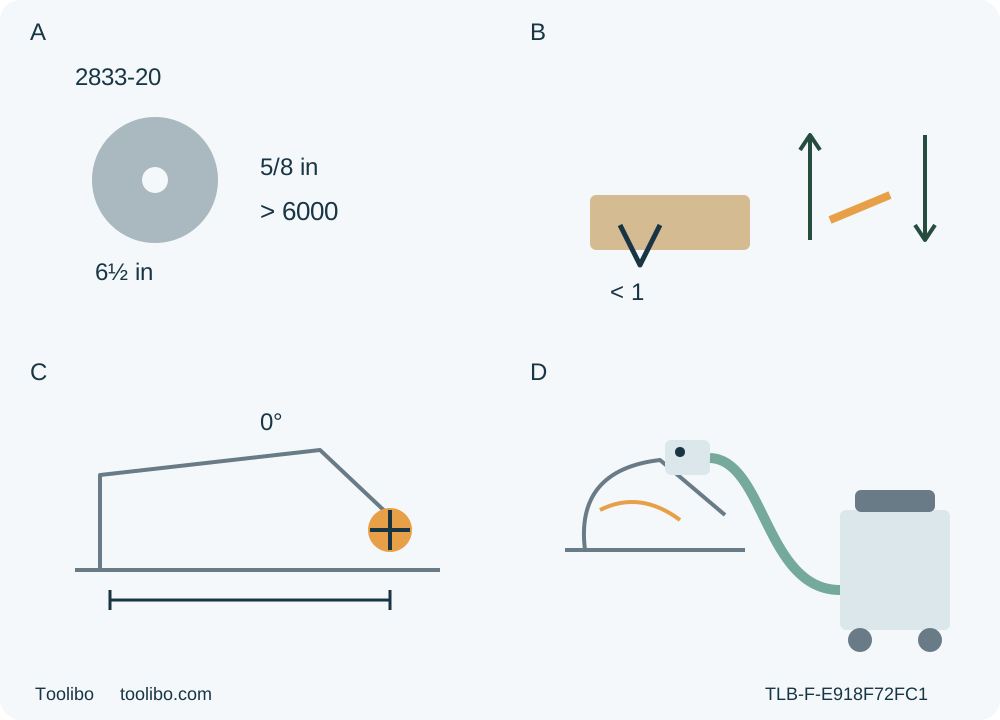
A identifies original 6-1/2-inch/5/8-inch blade with strict speed qualification. B shows depth lever up/down and partial tooth. C distinguishes the front bevel knob at zero. D shows complete native extraction.
A · Qualify the original blade
Original approved 6-1/2-inch/5/8-inch wood assembly, blade rating greater than actual nameplate 6000 RPM; no fitting recipe.
B · Lock actual partial-tooth depth
Battery removed: lever UP toward motor releases, DOWN locks. Verify actual through-cut with less than full tooth and support clearance.
C · Distinguish the bevel knob
Battery removed: front bevel knob sets and locks zero; verify existing square relationship without an alignment-screw recipe.
D · Require the complete vacuum route
Already qualified native adapter and secured hose to active appropriate extractor; saw and extractor isolated during connection checks, no bare outlet.
Original conceptual recognition, not to scale or a blade/adapter installation sequence. A requires a blade rating greater than the actual nameplate speed, documented 6000 RPM. B represents UP release and DOWN lock, with actual through-cut but less than a full tooth; the broad depth illustration is not a fixed target. C is the separate front bevel knob. D depicts the selected already qualified adapter/hose/vacuum route, not permission for a bare outlet or a universal hose fit.
The Milwaukee 2833-20 is a 6½-inch M18 FUEL circular saw with its own blade-speed qualification, depth lever and dust-outlet requirement. It is not a smaller version of a 2834 procedure, nor permission to reuse every instruction from an older 2630. This guide finishes one modest square crosscut in known loose wood, using an original qualified assembly, an already commissioned power system and the native vacuum arrangement.
Match the actual US 2833-20 to manual 58140235d2, dated 09/25. The current product links a file named 58-14-0235.pdf; the footer, rather than the filename alone, identifies the revision. Read the complete applicable tool, blade, battery, charger and extractor instructions before proceeding. Unknown identity or controls means HOLD for clarification, not a trial based on appearance.
1. Qualify the original blade, power and dust system
Retain only the original approved wood-cutting assembly already correctly installed for this tool: 6½-inch blade, 5/8-inch arbor, correct original flanges and bolt, and the documented orientation. The blade’s maximum safe operating speed must be greater than the no-load speed on the actual nameplate; the documented tool speed is 6000 RPM. A blade marked only 6000 does not satisfy that strict rule. A larger speed number does not establish correct application, hole shape or hardware. Read the actual blade manufacturer’s instructions as well.
This is not a blade-change guide. Do not infer a bolt direction or torque from another Milwaukee saw or convert an arbor opening. Dullness, cracks, broken teeth, a bent blade, incorrect washers, questionable tightening or an unidentified replacement require qualified correction before use. Abrasive cut-off wheels and dry diamond blades are excluded. Keep the original cutting edges sharp and clean under the complete instructions; there is no sharpening or internal-cleaning recipe here.
The owner must already have a genuine, specifically designated M18 battery and the charger specified for that battery, commissioned under their own complete instructions. The saw lists M18 battery and charger types, not a universal approval for anything that slides into the housing. This workflow does not select a new pack, teach charging or turn FORGE marketing into a safety qualification. Do not use damaged or modified equipment. Protect detached battery terminals from loose metal and resolve leakage, damage or doubtful history before use. The manual recommends an ambient operating range of 0°F to 125°F; do not reinterpret it as a charging-temperature range.
The manual requires either the dust chute or the vacuum hose adapter with a vacuum whenever operating. A bare outlet is not an acceptable third option. This workflow chooses the complete native vacuum route: the original appropriate adapter already installed correctly, its securing screw properly qualified under the exact instructions, a compatible hose positively secured and an appropriate extractor. The manual’s 0.9 ft-lb value concerns the adapter screw only; it is not a blade-bolt torque or permission for a partial retrofit. The word “universal” does not prove that every hose or extractor fits.
If the native system is missing, loose, obstructs the guard or cannot meet the actual material’s dust requirements, HOLD before cutting. Do not substitute a nearby loose vacuum hose or remove the outlet hardware to improve the view. The alternative chute is documented, but changing to that arrangement is not the operating route taught here.
2. Remove power and inspect the actual guard
Release the trigger, wait for complete standstill and keep the tool off. Press the battery release buttons and pull the battery away. Remove it whenever the tool is not in use, and before adjustments, accessory work or inspection. A brake, lamp or lock-off is not isolation. Keep the pack separate while planning the cut and checking the tool.
Inspect the tool for undue noise reported during prior use, loose or broken parts, binding, misalignment, bent shoe, damaged controls and any unexplained condition that could affect operation. Do not energize a suspect tool to reproduce a fault. An unreliable switch, damaged lock-off or abnormal assembly requires service before the sample.
Use the model’s actual isolated lower-guard check: place the tool on its side, grasp the lower guard by its sides, push it fully back into the blade housing and release. Keep fingers away from teeth and pinch points. The manual explicitly says this check does not show proper operation if the tool is not on its side; do not borrow the blade-up orientation from the blade-fitting section. The guard must spring back immediately. Check the lever and spring, and verify that the guard moves freely without touching the blade or any other part at all angles and depths of cut, including after a drop.
Sluggish return, interference or uncertain spring action means HOLD for qualified cleaning or service under the complete instructions. This guide does not describe dismantling or working inside the guard. Never tie or clamp it open. After setting the actual sample depth and angle, recheck that configuration too. For an ordinary edge-entry cut, the lower guard must work automatically, not be held open by a hand.
3. Choose a controllable crosscut and support it
Select sound, dry, known wood approved for the actual original blade. Inspect the route and remaining stock for nails, stones and other foreign material; hard inclusions can damage teeth and make the blade wander. Exclude unknown coatings or treatments, hidden services, installed structures and nonwood materials from this sample. Do not apply cutting oil. Choose a modest thickness and length that allow stable two-hand control, not a maximum-capacity demonstration.
Use a clean, well-lit, dry work area, away from rain, wet conditions, flammable materials and explosive atmospheres involving liquids, gases or dust. Keep bystanders and children clear. Wear eye protection marked ANSI Z87.1 and appropriate hearing protection. In dusty conditions the manual requires an OSHA-compliant extraction solution operated under its instructions or appropriate respiratory protection; this owner route additionally requires the selected native vacuum system to be connected and active. Provide suitable ventilation and material-specific respiratory protection where required. A connected adapter does not itself establish occupational dust compliance.
Clamp the retained stock securely to a stable bench or sawhorse arrangement. Support both future portions outside the blade path so neither sags into a closing kerf. The offcut must remain independently supported and free to separate; do not clamp across the cut or catch waste by hand. Position supports near the cut and outer edges as the actual work requires, without cutting the supports. There is no universal safe overhang or load rating in this guide.
Mark the wanted end from a reliable reference and identify the waste side. Keep the shoe supported on the retained work through entry, travel and planned exit. If an existing straightedge is used, it must be securely clamped, correctly positioned for the actual shoe-to-cut relationship and clear of motor, guard, handles and hose. Do not borrow another saw’s offset or assume a sight line is a measured guide setting.
With the battery removed, blade guarded and teeth clear, check stance, reach, hose path and all clamp clearances beside or safely above the intended path. Do not push the projected blade through uncut stock during this check. Reject a setup that requires releasing a handle, leaning across the blade, losing shoe support or moving a clamp mid-cut. A larger bench or different stock arrangement is preferable to improvising at the exit.
4. Set zero, verify square and lock actual depth
Keep the battery removed. Hold the saw by its handle, loosen the front bevel-adjusting knob, set the pointer to zero and tighten the knob securely. This knob is not the depth lever. Verify the existing blade-to-shoe square relationship using the manual’s isolated check: on the blade side, retract the guard with safe finger clearance and place a square against blade and shoe. Restore the guard afterward. If alignment is wrong or the check cannot be performed safely, obtain qualified correction; this guide does not turn the alignment screw or teach calibration.
To adjust depth, push the depth lever up toward the motor housing, move the shoe to the needed position and press the lever down to secure it. Check that it stays locked. The general safety rule requires less than a full tooth visible below the material. The depth section also prints a broad 1/8-to-1/4-inch projection description and a 6 mm illustration; those do not authorize exposing an entire tooth. Set an actual through-cut that satisfies the stricter partial-tooth condition and clears every support beneath the work. Do not force a minimum projection from the broad numeric wording.
Product depth-detent descriptions are not a substitute for this real projection check, and this guide does not invent a detent-operating sequence. Recheck depth and both adjustment locks after changes. Line up the actual square-cut sight line with the marked route; no left/right notch assignment is guessed from another model. Confirm the retained side, waste and clear exit before reconnecting.
5. Activate the qualified system and make the sample
Keep the saw off, fully stopped and battery-free, and isolate the extractor under its own instructions while checking the native adapter and hose connection. Confirm the existing adapter is secure and the hose positively locked, with enough free travel but no loop that can pull the saw, obstruct a grip or interfere with the guard. Operate and check the extractor under its own instructions before cutting. An off vacuum attached to the port is not active dust control.
With the trigger released and the tool off, slide the commissioned battery into the housing until it latches securely; verify secure engagement without forcing it. Remove setup tools. Do not proceed if any control, latch or connection is uncertain.
Hold the main handle with one hand and the front handle with the other, keeping hands clear of the blade and all moving parts. Use insulated gripping surfaces when a cutting operation could contact hidden wiring; this sample excludes such a route. Keep hands out from under the work and never hold stock or waste. Position your body to either side of the blade line, not directly in line with it, with arms able to resist kickback.
Place the front of the shoe on the supported work edge with the blade clear of the material. Align the actual sight line. Push the lock-off button down while pulling and holding the trigger, and allow full speed before contact. Advance smoothly forward across the grain, keeping the shoe flat and both grips firm. Use a pace that avoids forcing and unnecessary splintering; do not lean harder to overcome slowing, twist the blade back onto the line or reach for the falling piece.
6. Separate normal completion from an interrupted cut
At normal completion, release the trigger and retain control until the blade stops completely before removing the saw from the workpiece. Confirm the lower guard covers the blade before setting the saw down. Remove the battery before inspection or handling cut pieces. Allow hot material to cool and account for sharp edges; do not immediately grasp the fresh cut simply because the motor is quiet.
If the blade binds, stalls or the cut must be interrupted, release the trigger immediately and hold the saw motionless in the material until complete standstill. Never pull a moving blade backward or lift it from a trapped kerf. Isolate before investigating. This guide does not teach a partial-cut restart, an in-kerf direction correction or a forced extraction; uncertain trapping or cause requires qualified help and a separately safe plan.
The electric brake engages on trigger release, but the manual expressly allows delay or a missed braking event. Frequent misses require authorized Milwaukee service. A “two seconds” estimate, the LED or silence is not permission to move the blade; observe complete stop. The brake never replaces the guard. Continuous overload can permanently damage the tool or battery and is not a normal cutting method.
7. Accept the result and retain the evidence
After isolation and cooling, check both faces and the cut edge for dimensional error, lack of square, wandering, splintering, burning and damage. Measure from the original reference, not the new edge alone. Check whether clamps or the guide shifted and whether the support, hose, guard or controls behaved abnormally. Accept the sample only if it meets the declared project requirement and the entire system remained normal; no numerical tolerance is promised here.
Record a failure instead of repeatedly cutting to see whether it disappears. Dull or damaged teeth, a bent shoe or blade, wrong blade, poor support or low battery can appear in the manual’s troubleshooting discussion, but a burn mark does not identify one cause by itself. Hold unexplained binding, smoke, blueing, noise or vibration for qualified assessment. Do not rescue a bad end by recutting a small loose piece.
For maintenance, unplug the charger and remove batteries from charger and tool. Keep vents clear and accessible surfaces clean, dry and free of oil or grease under the complete instructions. Use only the prescribed mild-soap/damp-cloth approach without liquid entering the equipment; never immerse it or use flammable solvents. Repairs and work outside those instructions belong with an authorized service facility. Store the isolated saw and protected pack securely. The finished outcome is a checked crosscut and a clear ready-or-hold decision for this exact original system, not a guarantee for other materials, packs or accessories.
Models referenced