
2630-20 isolated owner checkpoints
Four conceptual panels show original blade identity above 3500 rpm, a side-position guard check with battery detached, depth lever down/up and the screw-mounted port on the shoe.
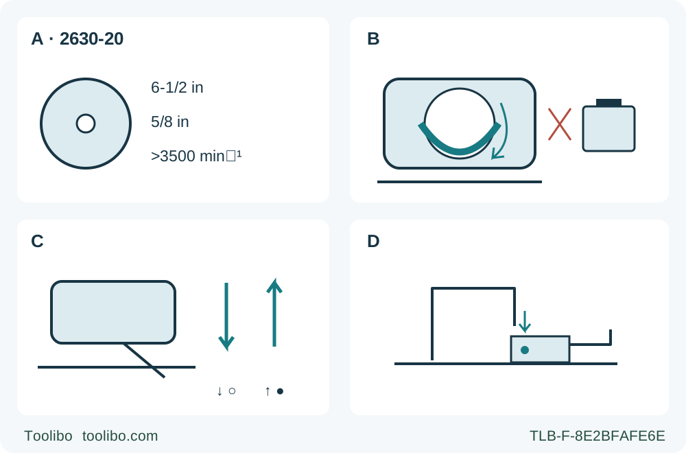
A · Original qualification
Match the original 6-1/2 in / 5/8 in thin-kerf wood blade, rated above 3500 rpm, and resolve the prior metal/masonry service gate before wood use.
B · Side-position check
Remove the battery, place the tool on its side and perform the complete documented guard check. The side-view symbol is not a blade-removal or live-test instruction.
C · Separate depth control
Battery removed: push lever 21 down toward the shoe to loosen and lift it toward the motor to lock. Verify both depth limits on actual stock; arrows do not replace those limits.
D · Shoe-mounted port
Battery removed: the specified port aligns with the screw hole on the shoe below the handle and is secured with the provided screw. Qualify the actual hose/extractor and full-path clearance.
B, C and D refer to a completely removed battery. B is an orientation and guard-return reminder, not a tooth-contact instruction; use the complete procedure. C arrows mean loosen down and lock up, with both depth limits retained in the text. D identifies the shoe mounting point without asserting a hose diameter. No panel depicts a running cut, blade fitting or a timed brake test.
This workflow qualifies an existing US Milwaukee 2630-20 for a manageable, square, edge-entry rip in clean loose wood. Its complete result is an accepted width and edge, together with a stable support and control record—or a clear hold before another cut. It is not a blade-change, charging or interrupted-cut restart tutorial.
Match the actual tool, controls and supplied instructions to the current product-linked 58142631d9 manual, revision 01/22. The filename contains 2631, but its cover and specifications identify 2630-20; that does not make another model interchangeable. Parts bulletins and older serial versions are not automatically covered. Keep the complete saw, battery, charger and dust-system instructions available. If identity or control behavior differs, resolve it before proceeding.
Establish the history and original assembly first
This body is rated 18 V DC and 3500 no-load rpm, with a 6-1/2 in blade and 5/8 in arbor. Retain the correctly installed original, sharp, appropriate thin-kerf wood blade and its qualified mounting parts. The blade-selection section requires a safe operating speed greater than the saw’s nameplate speed: use an original blade rated above 3500 rpm, not merely equal to it. Read its manufacturer’s instructions and confirm approval for the actual wood and rip.
Cracked blades, broken teeth, damaged or incorrect washers or bolt, uncertain orientation and unknown assembly history stop this workflow. The general diamond-versus-round warning does not authorize a different arbor. Nor do the manual’s later masonry passages cancel the blade-selection prohibition on dry-diamond or abrasive substitutions. This guide is wood-only and does not resolve those passages into a nonwood procedure.
Ask what the saw has previously cut. The manual requires a saw used for masonry or metal to be reserved and marked for that purpose and returned to a Milwaukee service facility for cleaning and testing before wood cutting. A clean-looking guard, new wood blade or acceptable test cut does not clear that history gate. Resolve unknown history; if the required service has not occurred, do not start this sample.
Use only the actual specifically designated, sound genuine M18 battery and its specified charger, already commissioned under their complete instructions. A shared platform name is not a new charger approval or capacity recommendation. Do not use a damaged or modified pack, and do not charge from this article. Release the trigger, wait for complete blade standstill, press the pack release buttons and withdraw the battery completely before checks or adjustments. Remove it whenever the tool is not in use.
Perform the model’s side-position guard check
Wear proper eye protection marked ANSI Z87.1 and keep fingers away from the teeth. With the battery removed, place the tool on its side. This orientation matters: the manual expressly says another position will not demonstrate proper lower-guard operation.
Following the complete instructions, grasp the lower guard by its sides, push it fully back into the housing without contacting the teeth, then release it. It must immediately spring back into place. Check the guard and lever condition and free movement without blade or other-part contact at all angles and depths of cut. Never tie or clamp the guard open; ordinary edge-entry cutting uses automatic guard operation.
If debris prevents immediate return, keep the battery out and remove chips and debris from the guards only within the documented cleaning scope, then repeat the same isolated check from the beginning. Persistent sluggishness, damage, an uncertain spring or an unsafe-to-perform check requires Milwaukee service before use. No powered guard test, spring repair or disassembly is part of this guide. A passing guard check does not certify the rest of a damaged or previously misused saw.
Lock depth and zero bevel independently
With the battery still removed, hold the saw by its handle and push depth lever 21 down toward the shoe to loosen it. Raise or lower the shoe for the actual material. The inner upper-guard scale has 1/4 in increments; it is an aid, not proof of tooth exposure. Lift the lever up toward the motor housing to lock the shoe securely.
Keep both depth instructions in view. General safety requires less than a full tooth below the work. The adjustment paragraph says the blade should extend no more than 1/8 to 1/4 in, and its drawing labels 1/4 in (6 mm). These are not interchangeable measurements. Use the shallowest setting that completes the cut while satisfying the tooth limit and the stated small-extension limit on the actual blade and stock. If that cannot be established, stop rather than assuming every tooth is 1/4 in tall. The full blade path must also clear every support.
For zero bevel, hold the handle, loosen knob 19, support the front of the shoe and rotate the saw by the handle to zero on scale 20, then tighten securely. A factory square setting is not a lifetime guarantee. The complete manual provides an isolated square inspection; doubtful alignment or a bent shoe remains a hold for the complete instructions or service, not a guessed adjustment-screw turn. Recheck both locks and guard clearance after setting.
Choose the correct rip route and secure the whole path
Choose manageable, flat, known untreated wood with an approved rip blade, no nails or other foreign material, and a sound reference edge. Mark the retained side, intended width and waste before placing a guide. This task deliberately uses a wanted rip width greater than 4 in. For that route the manual permits a straight piece of 1/2 in lumber as a shoe-edge guide. Clamp it securely; this workflow does not use the alternative tacking method.
For widths of 4 in or less, the manual instead specifies a rip fence. Do not transfer this wider-rip arrangement to a narrow strip or assume a fence came in the carton. Change the task or use the complete appropriate documented arrangement. Choosing a wider sample does not by itself guarantee enough support or hand clearance.
Clamp the work to a stable bench or sawhorse arrangement. Support retained material and waste independently near the cut and panel edges as needed to prevent sag, with supports outside the tooth path. Keep waste free to separate rather than clamping the kerf closed. The broad shoe must remain flat on supported retained material through entry, travel and exit. No person should hold the waste, and no cut should require releasing a clamp or changing grip while running.
Measure the actual blade-to-contact-edge relationship at zero bevel and qualify it on matching scrap. Align sight line 13 with the intended route, but do not assume the mark or another saw’s offset guarantees the finished width. Secure the guide so the blade removes material on the waste side. Check the guide is straight and that clamps, hose and the entire underside remain clear. With battery removed and blade guarded, assess reach beside or safely above the route, without tooth contact; do not push exposed teeth through uncut wood as rehearsal.
Qualify dust control before the sample
Use suitable hearing and respiratory protection, ventilation, stable footwear and a clean, well-lit work area with bystanders clear. The manual calls for appropriate respiratory protection or an OSHA-compliant extraction solution in dusty situations; neither a hose fit nor a lack of visible dust proves compliance.
This workflow uses a complete compatible extraction arrangement whose actual instructions and suitability are established. With the battery removed, the specified port mounts at the screw hole on the shoe below the handle: align the port and shoe holes and secure with the provided screw. Confirm the proper port, compatible hose and suitable extractor are present and correctly used. No universal hose diameter, substitute screw or borrowed Bosch airflow threshold is supplied here.
Arrange the hose so it cannot pull the saw sideways, foul the lower guard, snag a clamp or enter the blade path. If the actual collection arrangement is unresolved, hold this extraction-equipped sample rather than treating it as optional. Dust controls do not remove the need to identify the material and use the protective measures required for it.
Cut normally, then accept the process as well as the edge
After all isolated checks pass, confirm the trigger is released and slide the commissioned battery into the tool until securely latched. Place the front of the shoe on the supported edge with the blade clear of the wood. Hold main handle 4 and front handle 1 with both hands, using the insulated gripping surfaces, with your body beside—not in—the blade line and arms positioned to resist kickback.
Push lock-off button 2 down while pulling trigger 3. Allow full speed before entering the wood. Advance forward evenly with the shoe flat and firm two-hand control; do not force, twist toward a wandering line or compensate for poor support with extra pressure. Binding, stall or any interruption requires immediate trigger release and holding the saw motionless until the blade completely stops. Never pull a moving blade backward. Isolate before assessing the cause; this guide does not teach an in-kerf restart.
At normal completion release the trigger, wait for complete blade standstill before removing the saw from the work, require lower-guard closure, set down safely and remove the battery before inspection. The electric brake is not a substitute for either condition. The manual describes a usual stopping time but also delay and missed braking; do not use a countdown as clearance. Frequent brake misses require authorized Milwaukee service, not repeated powered fault tests.
Measure width at entry, middle and exit, check edge straightness and squareness to the face, and inspect splintering or burning against the intended use. Record whether the guide stayed fixed, both portions remained supported and the shoe, grips and hose stayed controlled. Correct width with pinching, support loss or abnormal behavior is not an accepted setup. Correct only an understood isolated setup issue under complete instructions; damaged parts, recurring faults or unresolved history require service.
Leave a usable owner record
Keep the model/revision, original blade identity, qualified power and dust arrangement, zero/depth settings and accepted guide relation with the sample record. Do not turn one successful cut into permission for narrow ripping, metal, masonry or plunge work.
For care, remove the battery and unplug the charger before maintenance. Keep vents free of debris and the tool clean and dry; the manual permits mild soap and a damp cloth, not immersion, liquid ingress or harsh/flammable solvents. Do not disassemble the saw, pack or charger. Follow its use-dependent inspection/service schedule and supply the model, serial, symptoms and prior material history when referring a fault. The next use still requires its own guard, assembly, support and control checks.
Models referenced