
Recognize the isolated M12 controls
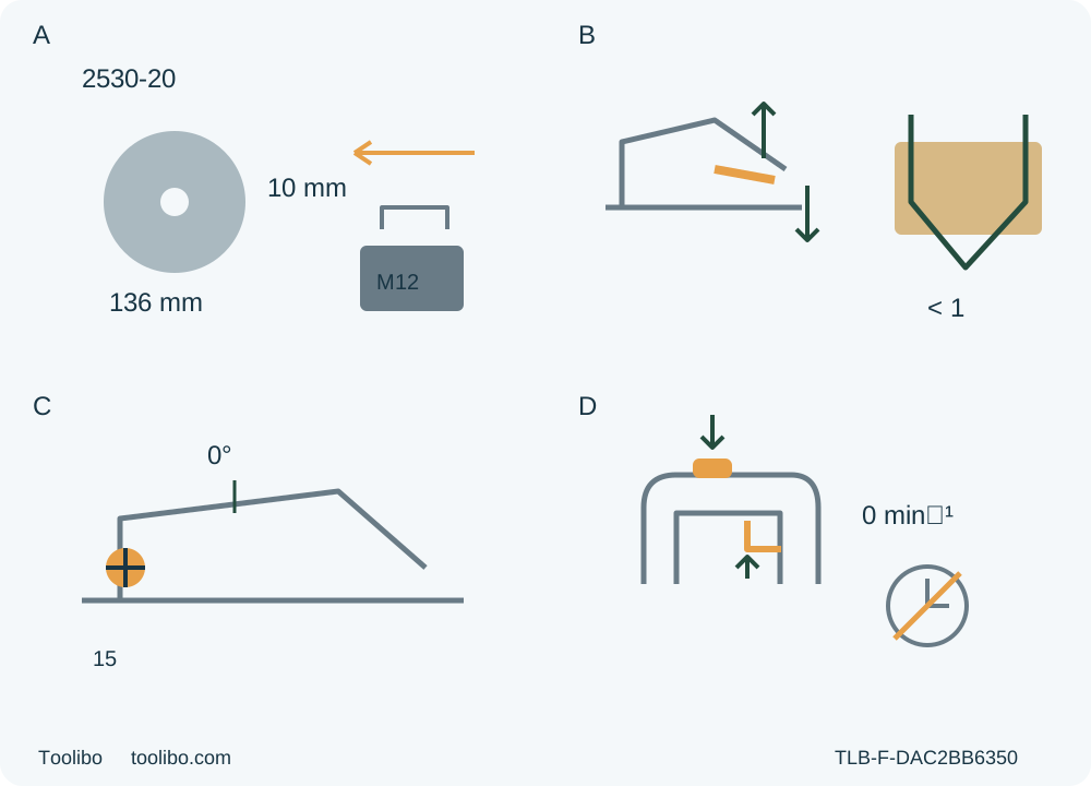
A shows original 136 mm/10 mm wood assembly and detached M12 pack. B shows depth lever up/down and less than a full tooth. C isolates the front zero-bevel knob. D separates downward lock-off and trigger recognition from actual standstill.
A · Qualify the original system
Original 136 mm/10 mm wood assembly and actual designated commissioned M12 power; blade rating strictly above actual nameplate, no replacement or charging tutorial.
B · Lock actual working depth
Battery out: rear lever UP toward motor releases and DOWN locks. Check through-cut, partial tooth and support clearance together.
C · Recognize the front knob
Battery out: front bevel knob sets and locks zero; square-check under exact instructions, no alignment-screw adjustment.
D · Separate start from safe handling
Actual normal start uses lock-off DOWN while pulling trigger with both handles. Release and wait for actual full stop before withdrawal; no two-second readiness rule.
Original concepts are not to scale, a blade-fitting sequence or a live cutting pose. B means actual through-cut AND less than a full tooth plus the manual upper projection limit, not a fixed millimetre setting. C is a separate knob, not the depth lever. D does not authorize an isolated trigger test or a timed brake test; actual complete standstill before withdrawal and guard coverage before setdown remain mandatory. No native dust port is depicted or inferred; the actual required dust solution is a pre-cut gate.
What this particular M12 owner can complete
This workflow ends with one supported, square, edge-to-edge crosscut in known loose wood, followed by an isolated inspection of the cut and the saw. It is for the actual US Milwaukee 2530-20 whose supplied instructions match 58142530d4, 07/18. It is not a recipe for a different M12 saw, a new battery system, an interior opening or a blade replacement. Read the complete matched tool, battery, charger and blade instructions first.
The starting assembly must already be the approved original 136 mm wood blade with a 10 mm arbor, correct original mounting hardware and an undamaged, properly operating tool. The manual also lists a 140 mm blade option; that does not authorize a change here. Its blade-selection rule requires a sharp, thin-kerf blade whose maximum safe operating speed is greater than the no-load speed on the actual tool nameplate. The specification table lists 3600 rpm. Do not substitute “equal to 3600,” use a motor number as proof of blade approval, or relax this wood-blade requirement because a later general-accessory paragraph says “at least.” Unknown blade markings, mounting condition or approval mean hold for qualified clarification before power is connected.
A small body does not remove the need for two hands, independent waste support or dust control. Nor does the brake make the blade safe to withdraw on a two-second countdown. Those are conditions of this whole task, not optional improvements after the first cut.
1. Qualify history, power and the environment
Establish the saw’s actual use history. The manual says a saw used for masonry or metal must be reserved and marked for that purpose and returned to a Milwaukee service facility for cleaning and testing before wood cutting. A wiped exterior is not that service release. Unknown contamination history is a hold, rather than a reason to try a small wood cut and see what happens.
Use only the actual designated M12 battery and the M12 charger specified for that battery, already commissioned under their own complete matching instructions. The product’s XC4.0 discussion is not a universal compatibility list or a promise about the owner’s carton. Record the actual pack and charger identities. An unidentified, damaged, modified, leaking or improperly functioning power component is not eligible. This guide does not teach charging or diagnose poor power by repeatedly pulling the trigger. The tool’s recommended operating ambient range is 0°F to 125°F; do not transfer that range to charging.
Prepare a dry, well-lit, uncluttered workplace with secure footing, no explosive atmosphere or flammable liquids, gases or dust, and no bystanders in the work or discharge area. Use ANSI Z87.1 eye protection, appropriate hearing protection and respiratory protection appropriate to the actual material and exposure assessment. Keep hair, loose clothing and jewelry away from moving parts. Do not work when tired or impaired.
Close the dust requirement before cutting. The manual’s considerable-dust applications require an OSHA-compliant dust-extraction solution operated under its own instructions. Its separate dusty-work instruction allowing appropriate respiratory protection or an OSHA-compliant extraction solution does not cancel that stronger requirement. The full tool manual does not identify a native port and adapter installation to copy here. Do not invent one, tape on a hose, infer compatibility from another Milwaukee model, or claim that a mask always substitutes for capture. Verify the actual applicable approved solution, ventilation, exposure controls and its safe relationship to the saw and work. If required capture cannot be provided or its suitability is uncertain, hold this task and choose a properly qualified alternative. A short cut is not automatically a low-dust application.
Any connection or clearance check for an already qualified extraction arrangement takes place with the saw off, fully stopped and battery removed, and the extraction equipment isolated under its own instructions. Activate and check that solution under those instructions before the cut. Its hose or other equipment must not obstruct the guard, grips, shoe, clamps, travel or exit.
2. Inspect the isolated original system
Release the trigger, wait for complete standstill, press the pack’s release buttons and pull the pack away from the tool. Keep it out for inspection, setting changes and alignment. The guard-check text uses the generic word “unplug,” but this cordless saw is physically isolated by removing its battery; do not invent a mains connection.
Inspect the original blade for dullness, cracks, broken teeth, contamination or distortion, and the accessible mounting hardware, shoe, handles, controls and housing for damage, looseness, binding or misalignment. A switch that cannot reliably control the tool is a service hold. Do not loosen the blade bolt, remove flanges, sharpen teeth or perform an energized fault test under this workflow.
The specific lower-guard check is done with the isolated tool on its side. With the blade safely clear and hands away from teeth, grasp the guard by its sides, push it fully back into the housing and release it. It must immediately spring back into place. This check does not work properly in a different tool orientation; the blade-facing-up illustration belongs to blade fitting, not this check. Verify free movement and no contact with blade or other parts at all angles and depths of cut, including the spring condition. Never clamp, tie or hold the guard open for an ordinary edge-entry cut.
The manual describes cleaning and rechecking a slow guard, followed by service if it still fails. This bounded owner guide instead stops for qualified correction when closure is not immediate; it does not provide a partial internal cleaning or spring-repair procedure. A successful check cannot erase a known drop, bent shoe or unexplained abnormal condition. Resolve those conditions before use.
3. Establish the square setting and real depth
Keep the battery out. Hold the saw by its handle, loosen the front bevel-adjusting knob, hold the front of the shoe and rotate the saw by its handle until the actual bevel pointer is at zero. Tighten the knob securely. Do not confuse this knob with the separate rear depth lever or with the rip-fence adjustment.
The manual’s square inspection sets zero, places the isolated saw on its blade side, retracts the lower guard and places a square against the blade and shoe. Qualify a stable supported position, keep fingers clear of teeth and use the actual flat references rather than a tooth tip. If the assembly is not square, hold for qualified adjustment; this is not an alignment-screw tutorial. Release the guard and verify its free return after the inspection.
For depth, hold the handle and push the depth-adjusting lever up toward the motor housing to loosen it. Raise or lower the shoe, then press the lever down to secure it. Check actual projection against the real stock thickness, not just the markings inside the upper guard. The blade must cut through the wood while less than a full tooth projects beneath it, with clearance from supports and equipment.
The depth paragraph also describes “no more than 1/8 to 1/4 inch” projection and shows a 1/4-inch/6 mm illustration. That broad wording is not a required minimum, a universal 6 mm setting or permission to expose a whole tooth. Retain the manual’s upper limitation as well as the stricter partial-tooth condition; if the actual assembly cannot satisfy through-cut, these limits and support clearance together, do not proceed. Recheck both locks, guard travel and actual depth after any setting change.
4. Plan one supported crosscut
Choose clean, dry, known solid wood approved for the installed blade, without nails or other foreign material along the full proposed route. It must be large enough to clamp securely and support the shoe throughout the cut, without placing a hand under the work or using a foot as a clamp. No loose small-part trimming, stacked stock, wall or hidden-material cutting is included.
Mark a square line from a trustworthy reference edge and identify the retained and waste sides. Clamp the retained stock securely on a suitable bench or saw horse. Support both portions near the cut and toward their edges, outside the blade path, so sagging cannot close the kerf. Support the waste independently while leaving it free to separate; do not clamp the two portions together across the kerf or reach to catch the offcut.
With the battery still out and blade guarded, assess the entire entry, middle and clear exit from beside or safely above the route without tooth contact or forcing the guard open. Check the actual shoe’s retained-side support, clamp clearance, both-grip reach, body position and any extraction equipment. Do not move a projected blade through uncut stock as an isolated rehearsal. If the setup requires an awkward reach, loss of support or moving a clamp mid-cut, change the supported plan before starting or hold the task.
Use the actual documented sight line and verify its relationship to the marked retained edge on equally safe scrap. This guide does not invent a left/right zero-notch assignment or a factory offset. The first sample must have the same qualified blade, zero setting, stock type and full support conditions as the intended cut. It is a controlled alignment check, not an invitation to steer sideways into a better line.
5. Make the normal cut and distinguish an interruption
Remove adjustment tools and confirm the trigger is released before inserting the qualified pack. Slide it into the body until it latches securely; verify retention without touching the trigger. A work light, pack indicator or latched pack is not evidence that the blade is safe to touch. Ensure the qualified dust-control arrangement is operating as required.
Place the front of the shoe on the supported work edge with the blade clear. Hold the main handle with one hand and the actual front handle with the other, keeping both clear of the guard’s movement. Keep hands out of the cutting area and from beneath the work. Position your body to either side of the blade line, with a stable stance and arms prepared to resist kickback. Align the sight line to the planned cut.
Push the lock-off button down while pulling the trigger, and let the motor reach full speed before blade contact. Maintain the two-hand grip, flat shoe and a controlled forward feed through the complete crosscut. Advance slowly enough to avoid unnecessary splintering; do not force the saw, twist it to correct the line, stop to relocate a clamp or use the free hand to hold waste. The lower guard operates automatically on this ordinary edge-entry route.
After normal completion, release the trigger and maintain control until the blade actually stops completely before withdrawing the saw from the workpiece. Confirm the lower guard has closed and covers the blade before setting the tool down safely. Remove the battery before measuring, clearing offcuts or inspecting the tool.
If the blade binds, stalls or the cut is interrupted, release the trigger immediately and hold the saw motionless in the work until complete standstill. Do not pull it backward or lift it free while the blade moves. Investigate the cause with the system isolated; a trapped tool or uncertain recovery needs qualified assistance. The manual contains a restart route, but this article does not teach old-kerf restart or partial-line escape.
The electric brake generally stops the blade within two seconds, but the manual explicitly allows delay or a missed engagement. Actual standstill, not elapsed time, controls withdrawal and handling. Frequent misses require an authorized Milwaukee service facility. Do not reproduce a suspected brake fault through repeated powered tests, and never use the brake as a substitute for guard coverage.
6. Accept the sample, or hold the system
With the battery removed, inspect the retained length, square relationship to the datum, full-depth separation, straight edge and damage on both faces. Compare them with the requirements you set for the actual job; this guide promises no numerical finish tolerance. Confirm that the supports did not shift, the waste separated freely, both settings remained locked and the guard still closes immediately.
A drifting line, blueing, smoke, burning, unusual sound, vibration or slowing is not cured by pushing harder or steering. The manual lists several possible causes, including blade condition, shoe alignment, support and low charge; a visible symptom does not diagnose one electrical fault. Hold use, record the actual symptom and obtain the appropriate qualified correction. Requalify a complete supported sample after a legitimate change rather than accepting the first successful millimetres as proof.
For care, remove the pack from the tool or charger and unplug the charger before maintenance involving that system. Keep vents and handles clean, dry and free of oil or grease. Follow the documented external mild-soap/damp-cloth care without immersion or liquid ingress; never use flammable or combustible solvents. Do not disassemble the tool, battery or charger. The manual calls for service inspection after six months to one year depending on use. Store the isolated tool securely with the blade guarded and the pack protected under its own instructions. Keep the model/manual, original assembly, power identities, dust qualification and accepted sample record together for the next task.
Models referenced