
Four isolated HS0600 qualification points
A identifies original 260 mm/5/8-inch assembly. B distinguishes front bevel lever and rear clamping screw. C shows partial tooth and actual zero sight reference. D contrasts the complete short-lever dust arrangement with the obstructing long lever.
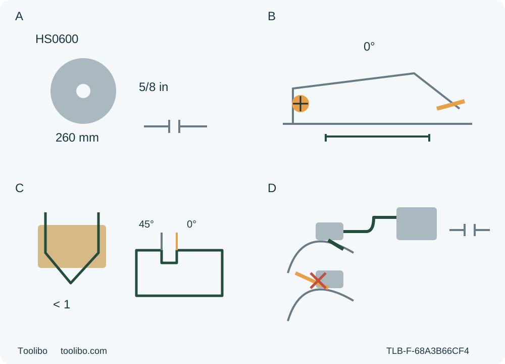
A · Match the original assembly
Original approved US 260 mm/5/8-inch wood assembly and rating already established; no ring/flange fitting or invented numerical blade threshold.
B · Lock both bevel points
Unplugged zero setting uses front lever AND rear clamping screw; both secure, existing alignment qualified.
C · Verify real depth and line
Depth-guide lever locks through-cut with less than a full tooth and support clearance; use actual front zero reference and a supported sample.
D · Require the complete dust system
Correct short guard lever plus secured nozzle and active suitable Makita extraction already qualified. Long lever obstructs the nozzle arrangement; no partial retrofit.
Original conceptual recognition, not to scale and not a blade-fitting, guard-lever replacement or nozzle-installation sequence. B requires both bevel fasteners secure at zero. C requires actual through-cut with less than a full tooth and clear supports; the sight reference is not a calibrated offset. D describes an already correctly completed native system: the short lever supplied with the nozzle is essential, and actual guard movement at all angles/depths must still pass. No hose diameter or part interchange is inferred.
A modest cut with the complete HS0600 system
The US Makita HS0600 is a distinct 260 mm, 10¼-inch corded body. Its advertised beam capacity is not the task here. This workflow qualifies an existing original system for one modest, supported square crosscut in clean, known loose wood, then checks the result with the tool unplugged. It requires the actual supplied 885547-940 / HS0600-1 / 20161012 instructions and matching physical controls. Read that complete manual and the actual blade, supply and extractor instructions before starting.
Two prerequisites deserve attention before any layout. First, the original approved US 260 mm/5⁄8-inch wood-blade assembly, including the correct country-specific ring and flange arrangement where applicable, must already be competently established. Second, this workflow requires the complete native extraction arrangement, including the short lower-guard lever supplied with the dust nozzle. The ordinary long lever obstructs guard movement when the nozzle is installed. An unknown blade arrangement or a nozzle combined with the wrong lever means HOLD, not “try a shallow cut.”
This is not a blade-fitting, lever-swap, rail, maximum-beam, calibration or repair tutorial. Those exclusions do not reduce the importance of the prerequisites; they identify work that must be properly completed before this owner route can begin.
1. Establish the actual assembly, supply and extraction
Identify the real tool, original approved wood blade, material suitability, blade rating and correct installed mounting hardware. Inspect the accessible blade and assembly for dullness, cracks, missing teeth, distortion, looseness or unexplained vibration history. The shared manual depicts ring and no-ring arrangements; it does not authorize the owner to choose a variant from a picture or reverse a flange to make another blade fit. If identity or condition is uncertain, obtain qualified correction. Do not infer an OEM minimum blade-rating rule from the 4300/min motor specification: this guide does not invent one.
Match the supply to the actual nameplate and use an intact matching plug, outlet and cord. The current US product identifies a 15 A tool, but the manual’s multi-voltage extension table is not evidence that every regional version accepts either supply. Any existing extension arrangement must be suitable for the actual nameplate, current, length and environment. For the table’s 120 V, over-12-through-16 A row, 25 ft uses 14 AWG and 50 ft uses 12 AWG; 100 and 150 ft are not recommended. Do not extend those entries by guesswork or modify a plug. Damaged supply equipment requires qualified service before use.
The optional dust-nozzle system is a mandatory qualification for this chosen workflow. It must already have been correctly installed with the supplied shorter guard lever, the nozzle secured by its screw, and a suitable Makita vacuum cleaner connected through the documented hose arrangement. Do not attach a hood to an ordinary long-lever tool, assume a different Makita nozzle or hose diameter, or follow a partial conversion recipe. If the complete actual arrangement and free guard movement cannot be verified, stop for qualified assistance.
Before checking hose connections or clearance, switch the saw off, wait for full standstill and unplug it; isolate the extractor under its own instructions. The hose must stay clear of guard travel, both grips, clamps, the shoe, feed path and free waste. Before cutting, operate and check the already qualified extractor under its own instructions. A connected but inactive hose is not active dust control.
2. Prepare the person, stock and whole support path
Use a dry, well-lit, uncluttered workplace with secure footing and no explosive atmosphere or flammable liquids, gases or dust. Keep bystanders clear. Wear eye protection, hearing protection and the appropriate dust mask required by the manual, with ventilation and material-specific exposure precautions. Extraction does not waive respiratory protection. Follow the material supplier’s safety information; unknown coatings or chemical treatment are outside this modest known-wood sample. Secure hair and clothing, and do not operate tired or impaired.
Inspect the entire proposed route for nails and other foreign material. Use sound, dry, untreated wood approved for the actual installed blade, of a manageable size that permits secure clamping and full control. Do not choose a large beam merely because the catalogue advertises a one-pass capacity. If the tool’s weight, reach or support demands exceed what you can control, stop and choose a properly qualified alternative arrangement.
Mark the square cut from a trustworthy datum and identify retained and waste sides. Clamp the retained stock securely on a stable platform; never hold the work across a leg or by hand. Support both portions near the cut and toward their edges, with all supports outside the blade path. Put the wider part of the base on the solidly supported retained material, not the portion that will fall away. Independently support the waste so it can separate without sagging into the kerf, but do not clamp the kerf closed or reach to catch it.
Plan a complete clear exit, not just a comfortable starting pose. With the saw unplugged and the blade guarded, assess entry, middle and exit from beside or safely above the intended route without tooth contact or forcing the guard open. Check both-handle reach, shoe support, clamp clearance and the full cord/hose paths. Do not push an exposed blade into uncut stock during an isolated rehearsal. A setup that needs mid-cut clamp changes, loss of support or an awkward reach is not ready.
3. Check the isolated tool and both bevel fasteners
Keep the tool unplugged for every inspection and setting change. Check the shoe, housing, both handles, accessible fasteners and controls. The front grip and rear handle must be secure; an uncertain or loose grip is a hold for proper correction, not an invented tightening torque. Do not use a tool with a damaged or unreliable switch, known defeated lock-off, abnormal binding or other unresolved damage.
Before each use, open the lower guard using its retracting handle, keep fingers clear of teeth, then release it and observe immediate closure. Check the spring and free movement without blade or other-part contact at all angles and depths of cut. Also verify that the retracting handle does not touch the tool housing. These checks are especially important with the installed short-lever/nozzle system. A slow, sticking or obstructed guard requires service before use. Never tie or hold it open for this ordinary edge-entry cut.
For zero bevel, the HS0600 has two separate fasteners: the front lever and the rear clamping screw. With the saw safely supported and unplugged, loosen both, set the actual bevel scale to zero by tilting the base as instructed, then securely tighten both. A tight front lever alone is not a complete setting. Verify the existing blade-to-base square alignment without contacting teeth. If it is not square, stop for qualified adjustment rather than using the maintenance adjustment screws or a powered “proof” cut here.
Set depth separately using the depth-guide lever: loosen it, move the base up or down to the actual stock thickness and tighten it securely. The blade must cut through while less than a complete tooth is visible below the work, with clearance from every support. This stricter safety requirement remains in force even though the later adjustment paragraph says “no more than one tooth.” A depth scale alone cannot prove actual projection. Recheck both bevel fasteners, the depth lever, guard return and real clearance after adjustment.
Use the actual 0° position on the front of the base for the square line; the 45° reference is not this task. Verify the real line relationship on a representative supported scrap sample. Do not borrow a notch shape, offset or guide setting from another Makita body. No rail or optional-fence fitting is part of this crosscut.
4. Start deliberately and complete the normal cut
Before every reconnection, while unplugged, check that the trigger operates properly and returns to OFF when released. Do not pull it hard without pressing the lock-off button. Remove adjustment tools and confirm the controls are released before plugging in. Never defeat the lock-off with tape or another device. A known history of starting on the trigger alone, without the lock-off, requires Makita service before further use; do not energize the tool to reproduce that fault.
Confirm the qualified extractor is operating and the work, waste, cord and hose remain as planned. Grasp the actual front grip and rear handle firmly, using the insulated gripping surfaces, with neither hand obstructing the guard. Keep hands away from the cutting area and underside, and never place a hand or body part behind the saw or under its base. Stand to either side of the blade line, balanced and prepared to resist kickback.
Set the base on the supported work with the blade clear of contact. Depress the lock-off button and pull and hold the trigger. Let the blade attain full speed before contact, then move the tool forward gently and straight, maintaining flat base support and a smooth feed until the crosscut is complete. The lower guard works automatically. Do not force, twist or steer back onto a wandering line, and do not press sideways against the blade to stop it.
After normal completion, release the trigger and retain control until actual full standstill before withdrawing the tool. Confirm the lower guard covers the blade before safe setdown, then unplug before acceptance or clearing waste. There is no timed-brake or lamp-state readiness rule in this workflow. A released switch does not make a coasting blade safe.
If the blade binds or the cut is interrupted, release the trigger immediately and hold the saw motionless in the work until it stops completely. Do not pull back or lift a moving blade. Isolate and investigate; a trapped tool, unexplained misalignment or uncertain recovery requires qualified assistance. This article does not teach old-kerf restart or a mid-cut line correction.
5. Accept the system through the sample, not a catalogue claim
With the saw unplugged, compare the sample with the actual task’s requirements: retained dimension, square relationship to the datum, straight edge, complete separation and acceptable damage on both faces. Inspect the support and clamp positions, free waste separation, retained depth and both bevel locks, and immediate guard return. No promised numerical tolerance or maximum-capacity performance is implied.
A burning cut, unusual sound, vibration, slowing, drift or guard interference is a stop condition, not a reason to push harder. Record what happened and obtain qualified correction without diagnosing an electrical fault from one symptom. An already incorrect assembly cannot be made acceptable by a neat-looking cut. After a legitimate change to blade, fixture, material or extraction, requalify the complete sample instead of inheriting the old result.
For care, switch off, wait for actual standstill and unplug the saw; isolate the extractor before its maintenance. Keep handles dry and free of oil or grease. The manual requires a clean guard system, but this bounded guide does not teach internal air-blast cleaning, blade removal or pitch solvents. If debris prevents correct function, keep the tool out of use until properly corrected. Do not use gasoline, benzine, thinner, alcohol or similar cleaners, immerse the tool or let liquid enter it.
The manual’s parallelism, zero-angle calibration and carbon-brush procedures are maintenance, not extra first-cut checks. Leave repairs and adjustments to the specified Makita service route. Store the unplugged tool securely with the blade guarded and the cord protected. Keep the exact model/manual, original assembly qualification, short-lever/nozzle evidence, supply details and accepted sample record together. That is a repeatable owner system; the headline blade size alone is not.
Models referenced