
Four checks before the sample
A shows an extractor connected by hose to the saw with the tool-end connection highlighted; B separates depth29 and both bevel7 locks; C highlights the left edge of zero CutControl mark with waste to the right; D identifies parallel guide 10 and securing bolt8.
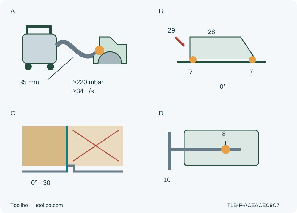
A · Verify installed extraction
Both required values must be established at the tool connection with the actual hose and extractor; use the qualified system actively under its instructions.
B · Isolate and lock the geometry
Remove the battery, set lever 29/scale 28 for less than a full tooth, secure depth and lock both bevel bolts 7 at zero.
C · Read the correct edge
Fold out CutControl 9; use the left edge of 0° mark 30 with waste to the right, then verify the actual kerf on scrap.
D · Secure the parallel guide
With battery removed, loosen 8, insert guide 10 through the base, set width at the corresponding mark and retighten 8. Confirm continuous edge contact and clearance.
Conceptual isolated controls, not a running-cut pose or scale drawing. A locates the required 220 mbar and34 L/s at the tool-end connection, not the vacuum outlet;35 mm is the recommended nominal hose. B does not prescribe an unsupported lever rotation. C uses the left edge of the 0° mark with waste right. D requires actual matched guide, battery removal, insertion, width setting and tightening before the sample.
A UniversalCirc 18V-53 is ready for an ordinary wood cut only when the installed blade, battery system, guide and dust extraction qualify together. This workflow uses the UK 06033B1400 identity, the currently linked D9C instructions dated September 25, 2025 and an already commissioned original assembly. The result is a measured square-edged strip from supported, known loose wood using the actual parallel guide—not a rail installation or a battery-platform compatibility experiment.
Match the actual system before setting the saw
Match UniversalCirc 18V-53 and the physical article number to the complete supplied instructions. D9C identifies the 3 603 CB1 4.. family; the separately linked UK declaration identifies 3 603 CB1 400. That declaration helps establish identity, not a new inspection or compliance certificate for your particular saw. Another region, older manual or similar green housing is not automatically interchangeable.
Retain the correctly fitted original approved wood-blade assembly. Its envelope is 160 mm diameter and 20 mm bore, maximum blade-body thickness 1.5 mm and maximum tooth thickness/offset 2.0 mm. The permitted blade speed must be higher than the saw’s 4300 rpm no-load speed, and the blade must meet the manual’s EN 847-1 requirement and suit the actual wood and cutting direction. These figures qualify an existing documented assembly; they are not a fitting recipe or permission to substitute washers, flanges or an apparently matching disc. HSS blades, abrasive wheels and ferrous-metal cutting are excluded.
The product and manual do not resolve every purchasing detail into one equivalent part. The current product lists an extraction adapter number different from the D9C connection overview; their weight figures also differ. Do not infer adapter interchangeability, a replacement blade order or a kit promise from this article. Unknown original assembly or extraction-part identity means hold and obtain the correct complete instructions or manufacturer confirmation before use.
Use only an already commissioned actual battery/charger combination whose complete instructions match the saw’s listed PBA 18V…W–. system and AL 18… CV guidance. D9C explicitly excludes AL 1814 CV, AL 1820 CV and AL 1860 CV for that battery. A recommendation of at least 2.5 Ah is not a claim that any smaller pack is universally unsafe, nor does a broad alliance logo establish a new pairing. Charging and first commissioning are outside this task; an unqualified or not-yet-prepared power system stops it.
Isolate, inspect and recognize the controls
Release the trigger, wait for complete blade standstill, press the battery release and pull the pack fully out without force. Keep it removed throughout guard inspection, settings, guide work, measurement and cleaning. The lock-off is not physical isolation. Keep detached terminals away from metal objects; damaged or modified packs must not be used. With the battery removed, inspect the original installed blade for dullness or damage and check accessible original mounting hardware and the tool’s condition. Keep cutting tools sharp and clean. A dull or damaged blade, loose or incorrect washers or blade bolt, abnormal binding or misalignment, or an unexplained condition requires qualified correction before use—not a powered fault test or refitting within this guide.
Use adjusting lever 14 for the lower-guard check with hands clear of teeth. Before each use the guard must move freely, close instantly and avoid the blade and other parts at all angles and depths of cut. Check its spring and condition. A bent, sluggish, damaged or obstructed guard requires service before use. Do not tie it open or use a running cut to test a suspect return. During the ordinary edge-start cut it operates automatically.
Identify insulated handle 17 and auxiliary handle 18, lock-off 4 and trigger 2. Confirm the controls operate correctly with the battery removed; an unreliable on/off control is a repair condition. Remove setup keys before reconnecting power. Keep grips dry and clean. The operating and storage temperature range is −20 to +50 °C, with limited performance below 0 °C; this is not the charging-temperature range.
The three charge LEDs are information, not clearance to ignore a fault. Three continuous green lights mean 75–100%, two mean 40–75%, one means 15–40%, and one slowly flashing light means 0–15%. Three rapidly flashing LEDs can indicate temperature outside the operating range and/or overload protection. Do not turn that combined indication into a definite diagnosis or an improvised reset. Stop, isolate when motion has ceased, and use the complete matched instructions or qualified service for the actual cause.
Establish working extraction at the tool connection
This sample uses a complete existing qualified external extraction arrangement. D9C requires both at least 220 mbar vacuum pressure and at least 34 L/s flow, equivalent to 122.4 m³/h, at the power tool’s dust-extractor connection. A vacuum’s free-air rating, maximum sealed suction headline, a hose that fits or suction felt by hand does not prove those installed values. Have the actual hose, connections, filter and extractor combination qualified under its instructions before cutting; if the requirement cannot be established, this task is on hold.
A 35 mm nominal hose and HEPA or dust-class-M filtration are recommendations in the table, distinct from the two required performance thresholds. They do not waive material suitability. Use the exact approved connection arrangement at chip ejector 16, including the actual qualified adapter/deflection-tube 21 route and hose 20 where required. The document’s accessory overview is not proof that a pictured vacuum achieves the thresholds with every hose configuration. No guessed part-number substitution or improvised reducer is taught here.
Connect the tool end and the extractor end with the battery removed. Arrange the hose so it cannot catch the guard, clamps, stock edge or your walking path, lift the base or pull the saw sideways. Operate and verify the already qualified extractor under its own instructions before the cut; a connected but inactive hose is not active extraction. Reduced suction requires stopping and eliminating the cause.
D9C prohibits working without dust-reducing measures, calls for ventilation and suitable breathing protection, and requires a special extractor for dry dust that is especially harmful to health or carcinogenic. Beech and oak require extraction explicitly. Use eye and hearing protection as well. This is not a claim that a numerical airflow pass alone makes every dust safe; unknown treated or contaminated material is outside the sample.
Set square depth and the actual parallel guide
Select sound, known, nail-free loose wood suitable for the installed blade and with enough width and length for stable clamping, full retained-base support and independent waste support. Establish a straight reference edge for the parallel guide. A bowed or damaged edge will be copied into the cut; do not try to fix it by pushing harder. Choose a sample whose retained strip remains wide enough for the actual base and guide arrangement rather than demanding an arbitrary narrow width.
With the battery removed, set depth using lever 29 and scale 28. Raising the saw away from base 13 reduces depth; moving it toward the base increases depth. Match the actual thickness so less than a full tooth projects beneath the work, then secure the depth lock and verify it cannot shift. The scale and 53 mm maximum square-cut capacity do not replace inspection of actual projection and underside clearance.
Both wing bolts 7 belong to the bevel setting. Loosen both, set scale 6 to zero and retighten both. Confirm the blade-to-base square relationship safely without touching teeth. Recheck guard freedom and depth after the angle is secured. This task does not use the 45° setting or transfer a square-depth reading to a bevel cut.
Fold the CutControl window 9 forward. For this square cut use the left edge of the 0° mark 30, not the center or the 45° mark 31; the manual’s diagram places the waste to the right. Make a sample to establish the actual blade/mark relationship instead of assuming the drawing represents your kerf width.
Use the exact sound parallel guide 10 that is already identified for the saw. With power isolated, loosen wing bolt 8, slide the guide’s scale through the base guide, set the desired width against the corresponding 0° cut mark and tighten bolt 8. Check that its edge-following face stays against the straight stock edge without obstructing the guard, clamp or housing. The scale gives a setting to verify, not a guaranteed finished dimension. Rail 32 and its joining, splinter-strip commissioning and special clamps are deliberately not used.
Rehearse the layout, then make one controlled sample
Clamp the retained work securely to stable supports. Support both resulting portions outside the blade path, with support near the cut and edges as appropriate to prevent sagging. Let the waste separate without closing the kerf; do not clamp the two sides together across it. Keep the broad base on the supported retained side through entry, travel and exit, not on the falling piece. Never hold the work on a leg or support an offcut by hand.
With the battery removed and blade guarded, check reach and clearance beside or safely above the intended path, without tooth contact or forcing the guard into uncut wood. Both designated grips must remain usable, and the hose must travel without drag. If guide contact, body position, underside clearance or full base support cannot be maintained, rebuild the setup before connecting power. No overhead, installed-stock, hidden-wall or table-saw use is included.
With the switch off, insert the already charged qualified battery until it clicks securely into place under its instructions. Start at the accessible edge with the base supported and blade clear of the wood. Grip both insulated handles firmly, keeping hands out of the cutting area, away from the underside of the work and out of the chip ejector. Keep the body to either side rather than in the blade line, press lock-off 4 and then press and hold trigger 2. The trigger cannot be locked on. Let the blade reach operating speed before entering, then advance uniformly and gently along the guide. Avoid forcing, twisting or allowing the motor to slow under excessive feed.
At normal completion release the trigger. The run-out brake shortens coasting but supplies no guaranteed stopping time; wait for actual complete standstill and guard coverage before setting the saw down. Remove the battery before measuring or repositioning. If the blade binds or the cut is interrupted, release the trigger and hold the saw motionless in the material until it stops. Do not pull a moving blade backward or improvise an in-kerf restart. Isolate, assess the cause and obtain appropriate correction before any later task.
Accept the width and the process together
Measure retained width at entry, middle and exit; check edge straightness and squareness to the face. Look for tearing, burning or changing kerf width, and confirm that the guide remained seated, both angle bolts and the depth lock stayed secure, and extraction continued effectively. A correct width at one end is not a pass if the guide shifted or the waste pinched the blade.
Correct ordinary setup errors only with the pack removed, then repeat on suitable scrap after changes that affect geometry. Unknown vibration, unreliable controls, guard interference or repeated binding remains a hold, not an invitation to sharpen, refit or reset within this guide. Record the accepted stock, original blade, guide width, depth and actual extraction combination. Clean accessible guard areas with a brush and keep ventilation slots clear with power isolated; this does not authorize blade removal or chemical cleaning. Store the isolated saw and protected battery under their complete instructions. The finished outcome is a repeatable qualified square-cut setup, not certification of every accessory or operation listed in the manual.
Models referenced