
Measure the full envelope in two views
Side and top views include the bit, body and dashed battery envelope, with example rulers and a withdrawal arrow.
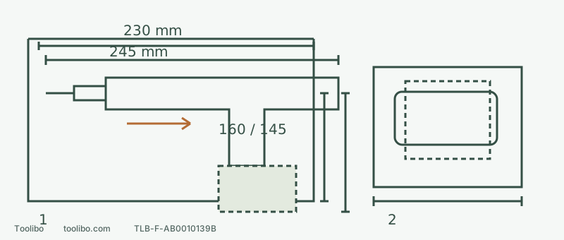
1 · Length and lower clearance
Check the correctly gripped accessory, battery underside and complete withdrawal path.
2 · Width and access
A narrow body does not guarantee battery, hand or doorway clearance; measure all three separately.
Not to scale; 245/230 and 160/145 are failed-fit examples, not DCD794 specifications. Dashed battery means a measured template with power disconnected.
List the assembly you actually intend to use
First look from a safe distance. If the battery is smoking, swollen, leaking or unusually hot, do not approach or handle it for an inspection; stop using the equipment and contact the manufacturer. Without those warning signs, record the DCD794 model, battery model, bit and any holder or extension. You are measuring that combination, not a single body-length specification. A wider battery or added holder can change the answer.
After an ordinary external check finds no damage, release the trigger, wait for all rotation to stop, put the direction button in its centre lock position and remove the battery. Install accessories and rehearse the route with the power disconnected; the lock button alone is not isolation.
Account for the removed battery without powering the drill
Put an undamaged battery separately on a stable bench and measure its length, width and height. Do not touch or bridge its contacts with a metal ruler. Draw its outline on cardboard, marking the mounting-face reference. This is a space template, not something to insert into the battery rails or connector.
Measure the disconnected body, the projection of the correctly installed accessory and the distance to the battery mounting plane. Add the battery outline to a side-view drawing using that reference. Make a top view too: battery width matters as well as height. Do not add an invented universal allowance, or connect the battery inside the cabinet just to see the assembled shape.
A full-size cardboard outline can check the route first; then use the disconnected tool to confirm hand and control access. Cardboard cannot verify chuck security or running behaviour. Those remain separate checks.
Check entry, the working position and the way out
Swipe or scroll horizontally to see all columns.
| Location | What to measure | If it fails |
|---|---|---|
| Door, rail or hinge opening | Full assembly height, width and turning room | Change the route or move a safely movable workpiece to the bench |
| Bit aligned with the intended hole | Clearance behind the motor, beneath the battery and around fingers and wrist | Rearrange the work; do not tilt the hole to dodge the tool body |
| Feed and withdrawal | Body travel, room to withdraw the bit and clamp interference | Choose a suitable alternative method or tool before starting |
You must be able to hold the tool, release the trigger and remove it completely after it stops. The battery may approach the cabinet floor during feed, while the rear of the drill can hit another panel during withdrawal. A check of the starting position alone misses these changes.
A cabinet example with measured numbers
Suppose your correctly clamped bit-to-tail assembly measures 245 mm, but the straight space behind the hole is 230 mm. These are hypothetical measurements illustrating the method, not DCD794 specifications. That combination cannot align straight, however compact the bare drill is.
Suppose the drawing also puts the battery’s lower edge 160 mm below the hole axis during the operation, while the cabinet floor is only 145 mm below it. That fails too. A different, explicitly compatible battery requires a new drawing and measurement; lower capacity does not automatically mean a suitable shape.
Set the tool only after the space check passes
With the battery removed, install the suitable accessory correctly and select a numbered clutch position for driving or the drill symbol for drilling. Mechanical speed 1 favours torque; speed 2 favours speed. Change ranges only at a complete stop and fully engage the selector. For ordinary screws, start at a low clutch setting on comparable clamped scrap rather than copying another project’s number.
Secure the work and remove templates, rulers and loose items. Keeping your finger off the trigger, install the specified battery and check that it locks, then select the required rotation. Make an observable trial in an accessible position before working in the restricted area. If the accessory loosens, the driver slips, the body touches an obstruction or straight alignment cannot be maintained, release the trigger and wait for a stop. Do not change accessories live in the gap. DCD794 does not inherit DCD799’s hammer mode, and reducing shank engagement is never a space-saving method.
Models referenced