
Shared platform, different owner controls
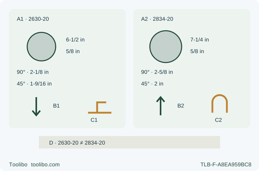
Paired 2630-20 and 2834-20 blade sizes and capacities, down versus up depth-loosening arrows, shoe versus upper-guard discharge symbols and an exact-model distinction.
A · Match the envelope
Compare each original blade diameter and documented capacity; the common 5/8 in arbor does not authorize swapping blades or fitting parts.
B · Opposite loosening directions
With batteries removed, B1 shows 2630 lever 21 loosening down toward the shoe; B2 shows 2834 lever 18 loosening up toward the motor. Locking is the opposite direction on each.
C · Different discharge systems
C1 identifies the 2630 shoe-mounted port; C2 identifies the 2834 upper-guard adapter. The latter requires adapter plus vacuum, or its permitted dust chute—not a bare opening.
D · Decide the exact system
Record original assembly, history, power, support and discharge prerequisites for each body; shared M18 naming is not operating or accessory interchangeability.
The two columns retain their own model identity throughout. B arrows indicate loosening only, with batteries removed, not blade travel. C is a mounting-location concept; it does not show every component or authorize an unconnected adapter. Both actual systems need their complete instructions. Capacity figures are documented limits, not measured performance or a bevel tutorial; no panel depicts a live cut.
Milwaukee 2630-20 and 2834-20 belong to the M18 family, but a platform name does not make their blades, controls or discharge arrangements interchangeable. This comparison builds a task-and-system decision for an owner considering supported square cuts in known loose wood. The result is an exact candidate with its prerequisites established, or a reason to hold—not a performance winner inferred from blade size.
The evidence is the US 2630-20 under current-linked 58142631d9 / 01/22 and the US 2834-20 under 58140586d4 / 12/24. Match actual labels, controls and supplied instructions before using either owner workflow. The 2630 manual filename contains 2631 but its cover names 2630-20. Neither this filename nor a shared battery family creates a different model, serial-version or regional equivalence.
Start with the actual cut and complete system
Write the material, thickness, width, cut direction, required edge quality and available support before looking at specifications. This scope uses dry, known, clean loose wood with an approved original wood blade; nails, foreign objects and uncertain coatings or treatment must be resolved. It does not select a tool for metal, masonry, internal plunge work or a restart in an interrupted kerf.
For each candidate, identify the actual specifically designated sound genuine M18 battery and its specified charger, already commissioned under their complete instructions. The saw manuals delegate charging details to those documents. A pack physically sliding into a tool is not the whole compatibility record, and this comparison makes no new capacity, runtime or universal charger approval. Include any missing qualified power equipment in the decision rather than comparing bare tool prices as complete working systems.
Also identify a suitable guide, stable retained-work clamping, independent support for both portions outside the blade path, clear travel and a feasible dust arrangement. Waste must separate without closing the kerf. If the location cannot accommodate these conditions, neither candidate is ready. A larger blade or a newer product name does not make an unsupported panel acceptable.
Compare the original blade envelope, not just the arbor
The 2630 specifications give a 6-1/2 in blade, 5/8 in arbor and 3500 no-load rpm. The 2834 specifies 7-1/4 in, 5/8 in and 6000 rpm. Both blade-selection sections require a blade safe operating speed greater than the tool’s no-load rating. Thus the original qualified wood blade must be rated above 3500 for the 2630 and above 6000 for the 2834; equality is not the stricter requirement in these selected passages.
The shared 5/8 in figure does not authorize swapping blades. Diameter, appropriate blade type, speed rating, original mounting parts, guard clearance and manufacturer approval still have to match. The 2630 specifically calls for thin-kerf blades. We retain each already correctly installed original assembly, without a flange, bolt, ring or replacement procedure. An unknown blade or altered mounting arrangement holds that candidate regardless of attractive capacity numbers.
For a square cut, the manuals list maximum depths of 2-1/8 in for 2630 and 2-5/8 in for 2834. Their 45-degree figures are 1-9/16 in and 2 in respectively. These are documented geometry limits, not measurements of cut speed or permission to force a thick cut. The selected owner task remains square; no bevel procedure is supplied here.
Use actual stock thickness and the required cut to screen candidates. If a task exceeds a model’s documented capacity, reject that proposed one-pass setup rather than improvising opposed cuts or removing protection. Being below the limit is necessary, not sufficient: the approved blade must cut through while the actual depth setting, supports and control remain suitable. A smaller body is not automatically easier to control, and a larger one is not automatically more accurate.
The depth lever directions are opposite
This is a practical reason not to operate from familiarity alone. With the battery removed, 2630 depth lever 21 moves down toward the shoe to loosen and up toward the motor housing to lock. On 2834, depth lever 18 moves up toward the motor housing to loosen and down to lock. Those arrows must remain attached to their exact model, not remembered as a Milwaukee-wide rule.
Both manuals pair the general less-than-full-tooth safety requirement with a depth paragraph stating no more than 1/8 to 1/4 in below the material. Do not replace one with the other or treat 1/4 in as a universal tooth height. Qualify the actual original blade and stock under both limits and lock the adjustment securely. A scale reading alone cannot prove projection or support clearance.
Each has a separate bevel knob and a factory square setting that still needs condition checks. Unknown base alignment, damage or a control that will not lock is a hold, not a reason to guess an adjustment screw. The comparison identifies these learning obligations; the exact owner guide and complete supplied manual provide the operating sequence.
The starting controls also differ. The 2630 uses a downward lock-off button with the trigger. The 2834 requires moving its trigger lock to the unlocked position before pulling the trigger. Neither control is physical isolation. Remove the battery completely for inspection, adjustment or accessory handling; do not substitute a lock position for that requirement.
Dust discharge is a complete arrangement
The 2630 manual locates its specified dust-port screw hole on the shoe below the handle. The port and shoe holes align and use the supplied screw, with the battery removed. Its admitted extraction-equipped owner task requires the actual compatible hose and suitable extractor to be qualified. No hose diameter or universal adapter is inferred from that drawing.
The 2834 has a different explicit rule: always use either the dust chute, or the vacuum adapter together with a connected vacuum. A bare discharge opening or an adapter without its vacuum is not an acceptable third option. Its vacuum adapter fits the upper guard, is screw-secured with the battery removed, and the hose connection twists together to secure. Do not move the 2630 shoe-port arrangement onto this body.
The chute option is genuinely permitted by the 2834 manual; it should not be falsely marked as prohibited. But a chute is not proof that the chosen room or material has adequate exposure control. For dusty work, both manuals require appropriate respiratory protection OR an OSHA-compliant dust extraction solution operated according to its instructions. Retain ventilation and safe dust handling; ANSI Z87.1 eye protection and appropriate hearing protection are separate requirements. If the planned work requires a compliant extraction solution, verify the actual system rather than assuming any vacuum qualifies.
For the decision, list which complete discharge option is available and where the hose or outgoing dust will go. Check that it will not foul the guard, snag clamps or pull the base off line. An unresolved system belongs in the hold column, even when the saw itself is otherwise suitable.
History and protective checks can override capacity
The 2630 manual contains a specific history condition: a saw used for metal or masonry must be reserved and marked for that purpose and returned to Milwaukee for cleaning and testing before wood use. An inexpensive used example with unknown prior cutting history therefore has a real unresolved prerequisite. A new wood blade, wiped housing or good-looking trial cut does not remove it. Do not transfer this wording into an unsupported claim about every other model; apply the exact supplied documents to the actual saw.
Both selected bodies require the isolated lower-guard check with the saw resting on its side, since another orientation does not demonstrate proper operation. They require immediate return and free movement without contact at all angles and depths. Persistent failure after the documented debris-cleaning check needs service. This is not a live guard test or permission to repair a spring.
Both manuals describe an electric brake that generally stops the blade within two seconds, but also warn of delay or a missed braking action. Neither gets a guaranteed stopping time in this comparison. Actual standstill and closed lower guard remain necessary before setdown; frequent brake misses require authorized service. Do not repeatedly energize a suspected fault to score which saw stops faster.
Write the choice and its exit conditions
Use one row per task requirement and two model columns. Record actual original assembly, capacity suitability, known history, qualified power, learned control directions, complete discharge arrangement, guide/support availability and unresolved service issues. Distinguish documented differences from preferences that would need separate safe handling assessment. Do not convert advertising output, speed or battery claims into a measured comparison.
For a wide rip, both manuals distinguish widths greater than 4 in, where a clamped 1/2 in lumber guide can be used, from 4 in or less, where the rip-fence route applies. That shared rule does not mean an offset transfers: measure and qualify each actual shoe-contact relationship with its original blade at zero. Missing the correct fence for a narrow task is a system gap, not permission to substitute the wide-rip arrangement.
A qualified 2630 may suit a task within its envelope when its history, original assembly and system are established. A qualified 2834 may be the candidate where its documented envelope or discharge arrangement addresses a real requirement. If both meet the task, this document review does not manufacture an ergonomic, price or speed winner. If either has unresolved safety prerequisites, mark it held rather than allowing a headline specification to compensate.
Finish by naming the selected exact model, evidence still needed, equipment or service required and the owner workflow to follow. Only after all prerequisites close should a normal supported sample confirm width, squareness, finish and stable process. On binding or interruption release the trigger and hold motionless until full stop; do not pull a moving blade backward or improvise a restart. The value of this comparison is knowing which complete system can responsibly enter that next step—not assuming that M18 means the same saw.
Models referenced