
HG6530V controls
LCD control, separate tool and sample readings, and cooling position.
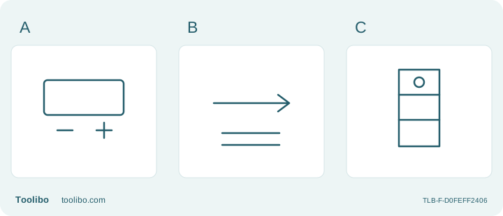
A
Buttons and LCD control the selected temperature.
B
Airflow information does not measure the supported object.
C
The top selector position represents the documented cooling state.
Position 1 is cooling at approximately 50°C; positions 2 and 3 are low- and high-flow heating. Persistent overheating indication after cooling and restart requires service.
Stay in the correct half of the manual
The US HG6530VK package links the HG6530V manual, which also describes HG6531C. HG6530V has temperature buttons and a slide switch. Do not import the neighboring model’s preset applications, confirmation button or language menu into its operating routine.
Make the first inspection entirely cold and disconnected. Match the nameplate, locate the switch and buttons, and compare them with the correct drawing. If they do not match, resolve the identity before continuing. A sales-package suffix does not make every model in a shared document the same tool.
Understand what the LCD reports
The checked HG6530V instructions say the display shows airflow temperature after the target is set. It does not measure the object. The upper face, underside and a bonded layer can respond differently even when the reading is steady. Material instructions and a sacrificial trial still determine suitability.
Temperature adjustment belongs to the applicable heating positions. The first position has a separate cooling role. Do not diagnose a lack of process heat in that position as a failed element, and do not force an unsuitable material to respond simply because a hotter setting is available.
Treat the kit as different air paths
The checked US listing includes four nozzle accessories and a case. Outlet shapes change how air reaches the work; they are not interchangeable decorations. Select an approved nozzle for the permitted application, fit it only when disconnected and cold, and leave an unobstructed path for air to escape around the sample.
A reflector used for a suitable non-electrical sleeve requires clearance around the object and support outside the hot zone. A broad nozzle changes the heated footprint. Whenever the accessory changes, treat the earlier trial as incomplete evidence and assess the new arrangement instead of automatically retaining the same exposure.
Respond to a blinking LCD without opening the housing
The manual identifies an overheating indication and directs HG6530V to cooling position 1, with restart only after complete cooling. If blinking continues after restart, it calls for a Makita service center. Apply that response only to the stated indication: a damaged lead, smoke from the tool or a failed fan does not authorize keeping powered cooling running.
Plan the standing cooldown before work. The manual also requires at least thirty minutes after shutdown before moving or storage. Do not touch the nozzle until actually cold. Before external care, ensure the tool is unplugged and cold. HG6531C programming, electrical diagnosis and internal repair are outside this guide.
Keep each reading tied to its context
An HG6530V trial note should state whether a number is the selected target or the later airflow indication. Otherwise someone may compare different kinds of reading and wrongly conclude that the tool is unstable. Include switch position, attachment and material so the note describes a process rather than an isolated number.
If an unexpected indication appears, distinguish the normal transition after selecting a new target from the specific overheating indication in the manual. Do not invent a universal meaning for every blink or change. Record what happened before and after it, and stop if the explanation does not match the applicable document.
Before a permitted restart after cooling, review the surroundings too. An attachment too close to an obstruction, or a sample blocking the air path, can recreate the problem. Move the work only when safe to handle, and do not replace an observed problem with a different unverified nozzle. If the symptom persists, the service boundary applies even when the tool still produces heat.
Read the verified operating values
For the US HG6530V, position 1 provides cooling airflow at approximately 50°C and 500 L/min. Heating positions 2 and 3 both permit 50–650°C selection, with 280 L/min and 550 L/min respectively. The operating instructions identify 2 as low-flow heating and 3 as high-flow heating. These tool settings are not workpiece temperatures; even the cooling position is warmer than room air and does not establish safe handling.
Models referenced